
Eureka
For R&D, Eureka makes reading and utilizing patents & technical documents easy.
Eureka AIR
Designed for self-driven R&D workflows. Generate viable solutions, solve complex R&D challenges, empower your innovation with AI.

Eureka Materials
Designed for material experts only. Revolutionize your material R&D, from search, analyze, to developing new materials.

TechResearch
Generate reliable direction feasibility study reports for your R&D in just a few steps.

TechSeek
Discover and master advanced knowledge NOW. Basics, ideas, possibilities, all at once.

TechMind
As an expert in R&D Theories, TechMind can generates customized viable solutions instantly.

TechRisk
Analyze your overall solution with one click, know your potential R&D risks in advance.

TechMonitor
Get weekly tech updates, stay abreast of the latest tech innovations and key insights.
Sheet conveyance apparatus, image forming apparatus and image forming system
- Summary
- Abstract
- Description
- Claims
- Application Information
AI Technical Summary
Benefits of technology
Problems solved by technology
Method used
Image

Examples
first embodiment
[0021]Now, a first embodiment will be described with reference to the drawings. In the following description, positional relationships in up and down, right and left and front and rear directions are described based on the image forming apparatus viewed from a front side, that is, from the viewpoint of FIG. 1.
General Configuration of Printer
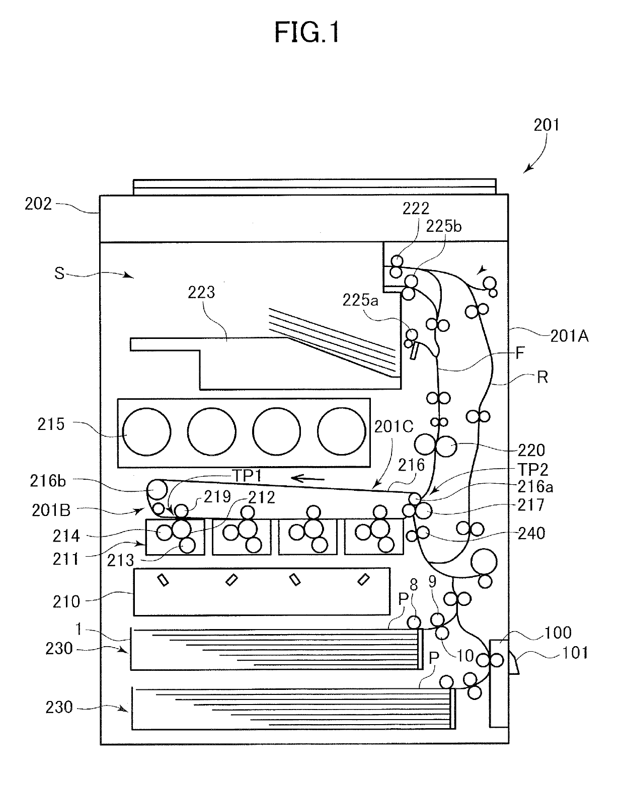
[0022]A printer 201 serving as an image forming apparatus according to the present embodiment is a full-color laser beam printer adopting an electrophotographic system. The printer 201 includes, as illustrated in FIG. 1, a printer body 201A serving as an apparatus body, and a reading unit 202 provided above the printer body 201A and reading image data from a document.
[0023]The printer body 201A includes an image forming portion 201B for forming an image on a sheet P, and a fixing unit 220 configured to fix the image on the sheet P. Between the reading unit 202 and the printer body 201A is formed a discharge space S to which the sheet P is dischar...
second embodiment
[0046]Next, a second embodiment of the present invention will be described. Compared to the first embodiment, the second embodiment changes the positional relationship of the stopper, the door and the pivot member, and the urging force of the urging spring. Therefore, the components similar to the first embodiment are either not shown in the drawing or denoted with the same reference numbers.
[0047]FIG. 7A is a side view illustrating a door 200 and the pivot member 110 positioned at a third position that is closer to a closed position with respect to the printer body 201A (refer to FIG. 2) than the first position. In the third position, the door 200 is opened to a third angle α3 that is smaller than the first angle α1 with respect to the printer body 201A (α1>α3). FIG. 7B is a side view illustrating the door 200 in the first position and the pivot member 110, and FIG. 7C is a side view illustrating the door 200 in the second position and the pivot member 110. That is, as the door 200...
PUM
 Abstract
Description
Claims
Application Information
 - R&D Engineer
- R&D Manager
- IP Professional
- Industry Leading Data Capabilities
- Powerful AI technology
- Patent DNA Extraction
Browse by: Latest US Patents, China's latest patents, Technical Efficacy Thesaurus, Application Domain, Technology Topic, Popular Technical Reports.
© 2024 PatSnap. All rights reserved.Legal|Privacy policy|Modern Slavery Act Transparency Statement|Sitemap|About US| Contact US: help@patsnap.com