Multi-Piece Polymer Ammunition Cartridge

a polymer and cartridge technology, applied in the field of ammunition, can solve the problems of inability to provide satisfactory ammunition, inability to meet the requirements of the type of cartridge,

Active Publication Date: 2019-05-09
TRUE VELOCITY IP HLDG LLC
View PDF3 Cites 76 Cited by
  • Summary
  • Abstract
  • Description
  • Claims
  • Application Information

AI Technical Summary

Benefits of technology

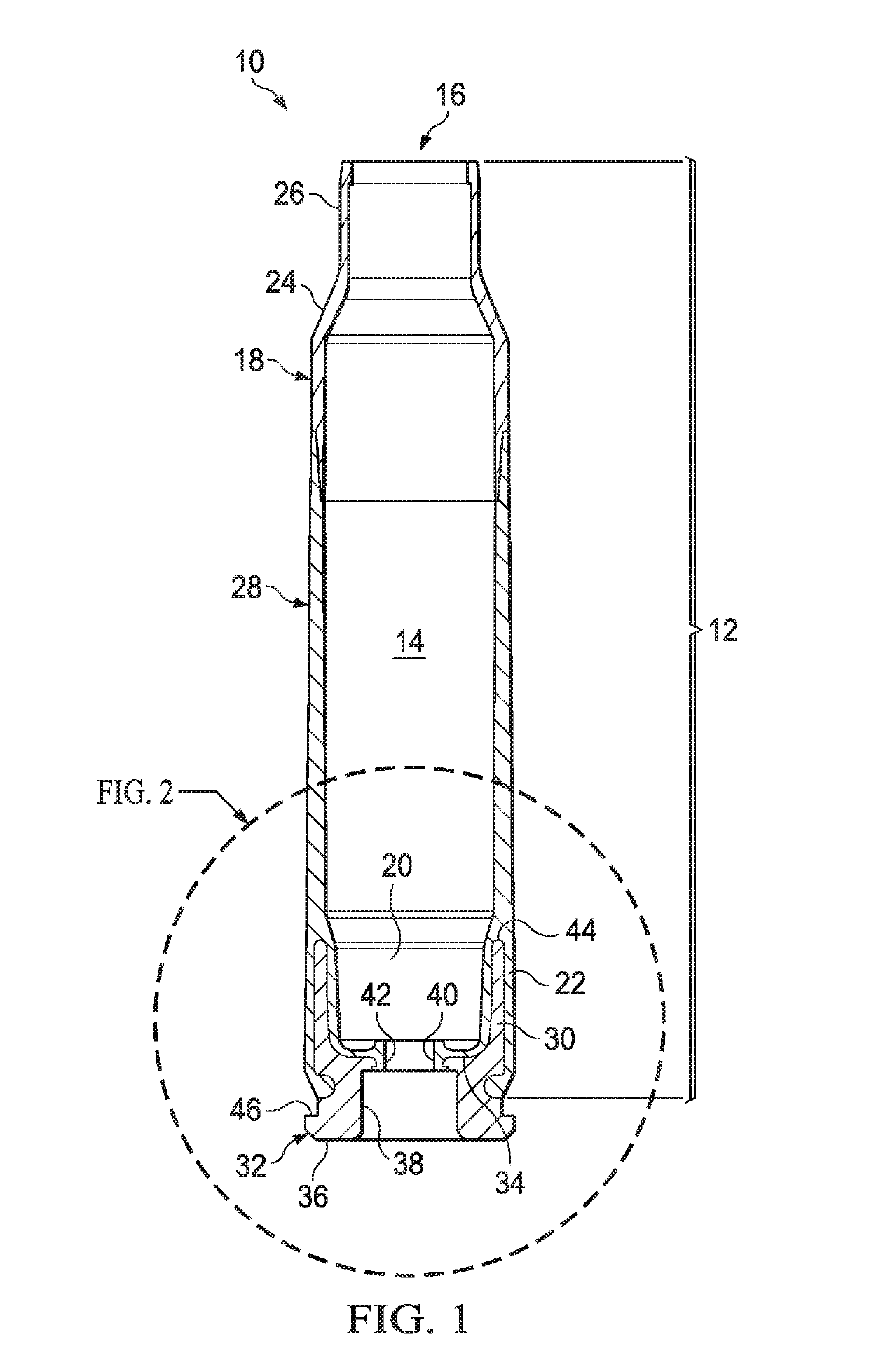
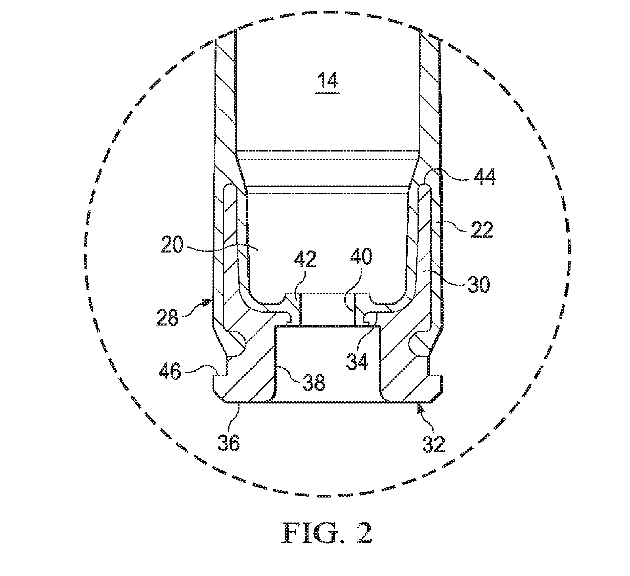
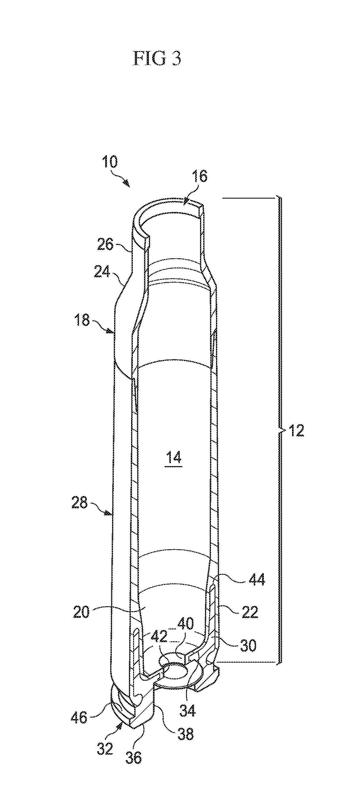
[0010]The nose junction is a groove and the skirt adjacent to the groove on the inside of the polymer nose and is adapted to mate to the body coupling. The nose junction is a half lap junction with the skirt on the inside of the polymer nose. The skirt is adapted to fit flush to a polymer cartridge. The includes an angle formed between the nose junction and the skirt is between 40 and 140 degrees. The angle formed between the nose junction and the skirt is about 90 degrees. The angle formed between the nose junction and the skirt is greater than 90 degrees. The angle formed between the nose junction and the skirt is less than 90 degrees. The shoulder comprises an outer shoulder surface having an outer angle opposite an inner shoulder surface having an inner angle and a skirt surface adjacent to the inner shoulder surface. The outer angle is the same as the inner angle. The polymer nose comprises a nylon polymer, polycarbonate polymer, polybutylene polymer or a mixture thereof. The polymer nose comprises a fiber-reinforced polymeric composite. The polymer nose comprises between about 10 and about 70 wt % glass fiber fillers, mineral fillers, or mixtures thereof. The polymer nose includes an adhesively groove is positioned in the projectile aperture. The polymer nose, the polymeric middle body or both individually comprise a polymers

Problems solved by technology

Conventional ammunition cartridge casings for rifles and machine guns, as well as larger caliber weapons, are made from brass, which is heavy, expensive, and potentially hazardous.
Plastic cartridge casings have been known for many years but have failed to provide satisfactory ammunition that could be produced in commercial quantities with sufficient safety, ballistic, handling characteristics, and survive physical and natural conditions to which it will be exposed during the ammunition's intended life cycle; however, these characteristics have not been achieved.
Shortcomings of the known method

Method used


Image

  • Multi-Piece Polymer Ammunition Cartridge
  • Multi-Piece Polymer Ammunition Cartridge
  • Multi-Piece Polymer Ammunition Cartridge

Examples


Embodiment Construction

[0027]While the making and using of various embodiments of the present invention are discussed in detail below, it should be appreciated that the present invention provides many applicable inventive concepts that can be embodied in a wide variety of specific contexts. The specific embodiments discussed herein are merely illustrative of specific ways to make and use the invention and do not delimit the scope of the invention.

[0028]To facilitate the understanding of this invention, a number of terms are defined below. Terms defined herein have meanings as commonly understood by a person of ordinary skill in the areas relevant to the present invention. Terms such as “a”, “an” and “the” are not intended to refer to only a singular entity, but include the general class of which a specific example may be used for illustration. The terminology herein is used to describe specific embodiments of the invention, but their usage does not delimit the invention, except as outlined in the claims.

[...


PUM


Abstract

The present invention provides polymeric ammunition cartridge having a generally cylindrical neck having a projectile aperture at a first end, an outer shoulder surface that extends from the generally cylindrical neck, an outer shoulder angle defined by the outer shoulder surface, an inner shoulder surface on the inside of the polymer nose opposite the outer shoulder surface, an inner shoulder angle defined by the outer shoulder surface, a skirt surface extending from the inner shoulder surface, a skirt angle defined by the skirt surface and a nose junction that extends from the outer shoulder surface to the skirt surface, wherein the nose junction is adapted to mate to a polymer cartridge.

Description

CROSS-REFERENCE TO RELATED APPLICATIONS[0001]This application incorporated the contents of each by reference in their entirety U.S. patent application Ser. No. 14 / 011,202 filed on Aug. 27, 2013 which is a Divisional Application of U.S. patent application Ser. No. 13 / 292,843 filed on Nov. 9, 2011 (now U.S. Pat. No. 8,561,543) which claims the benefit of U.S. Provisional Patent Application Ser. No. 61 / 456,664, filed Nov. 10, 2010.[0002]This application claims the benefit of U.S. patent application Ser. No. 15 / 808,859, filed Nov. 9, 2017.TECHNICAL FIELD OF THE INVENTION[0003]The present invention relates in general to the field of ammunition, specifically to compositions of matter and methods of making and using polymeric ammunition cartridge casings having at least 2 portions.STATEMENT OF FEDERALLY FUNDED RESEARCH[0004]None.INCORPORATION-BY-REFERENCE OF MATERIALS FILED ON COMPACT DISC[0005]None.BACKGROUND OF THE INVENTION[0006]Without limiting the scope of the invention, its backgroun...

Claims


Application Information

Patent Timeline
IPC IPC(8): F42B5/307F42C19/08
CPCF42C19/083F42B5/307F42B33/00F42B5/285F42B5/36F42B5/313
Inventor BURROW, LONNIEOVERTON, CHRISTOPHER WILLIAM
Owner TRUE VELOCITY IP HLDG LLC
Why Eureka
Try Eureka