
System of RFID reader units transmitting synchronized modulation using asynchronous carrier waves

a technology of asynchronous carrier waves and rfid reader units, which is applied in the field of system of rfid reader units, can solve the problems of compromising read, complex and expensive hardware, and less ideal in certain use cases, and achieve the effect of efficient enhancement of the coverage area and read performance of the rfid system

Active Publication Date: 2019-05-09
N V NETHERLANDSCHE APPNFAB NEDAP
View PDF0 Cites 232 Cited by
  • Summary
  • Abstract
  • Description
  • Claims
  • Application Information

AI Technical Summary

Benefits of technology

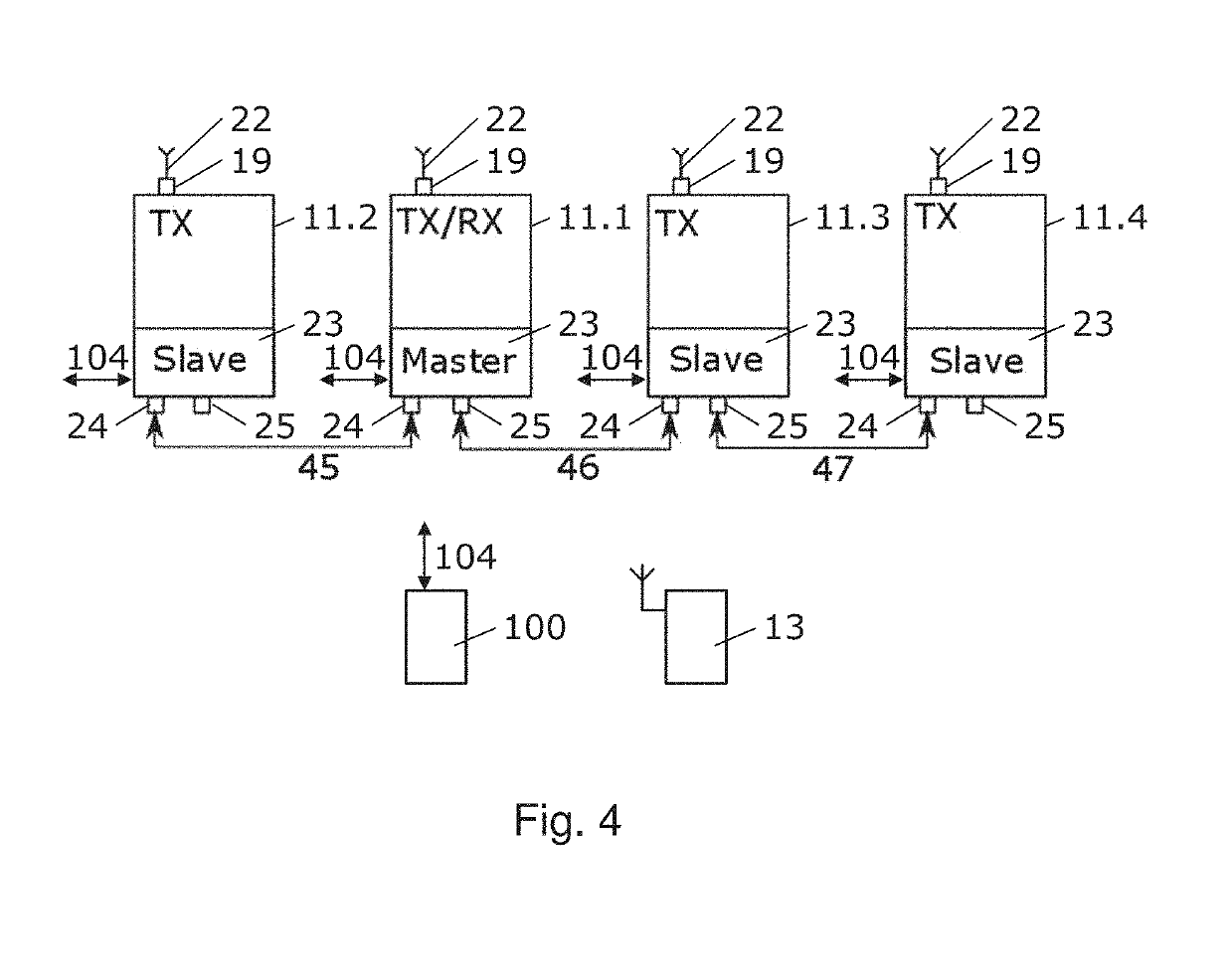
This patent is about a system that allows multiple RFID readers to work together, increasing the coverage area and read performance of the RFID system. The system uses independent carriers for each reader, which are synchronized with each other. This approach is more efficient and cost-effective than other methods. By using unsynchronized carriers, the system provides full coverage in a given area, instead of a checkerboard pattern. The reader units can be installed as master or slave, making installation easier. They can also be configured as transmitters, receivers, or transceivers, making installation even easier.

Problems solved by technology

A disadvantage of this system relates to modulation depth issues compromising the read rate
However, all of them have several disadvantages which make them less ideal in certain use cases.
In many situations this is undesired due to the added costs of high quality coaxial cabling and installation.
However, this solution requires complex and expensive hardware.
Additionally, to achieve full field coverage with coherent transmitters, dedicated phase shifters are needed to move the interference hotspots and zeroes through the area, adding to the complexity of the hardware and the time needed for a full inventory.
Furthermore, it is unclear whether coherently transmitting readers will pass the regulatory requirements.

Method used


Image

  • System of RFID reader units transmitting synchronized modulation using asynchronous carrier waves
  • System of RFID reader units transmitting synchronized modulation using asynchronous carrier waves
  • System of RFID reader units transmitting synchronized modulation using asynchronous carrier waves

Examples


Embodiment Construction

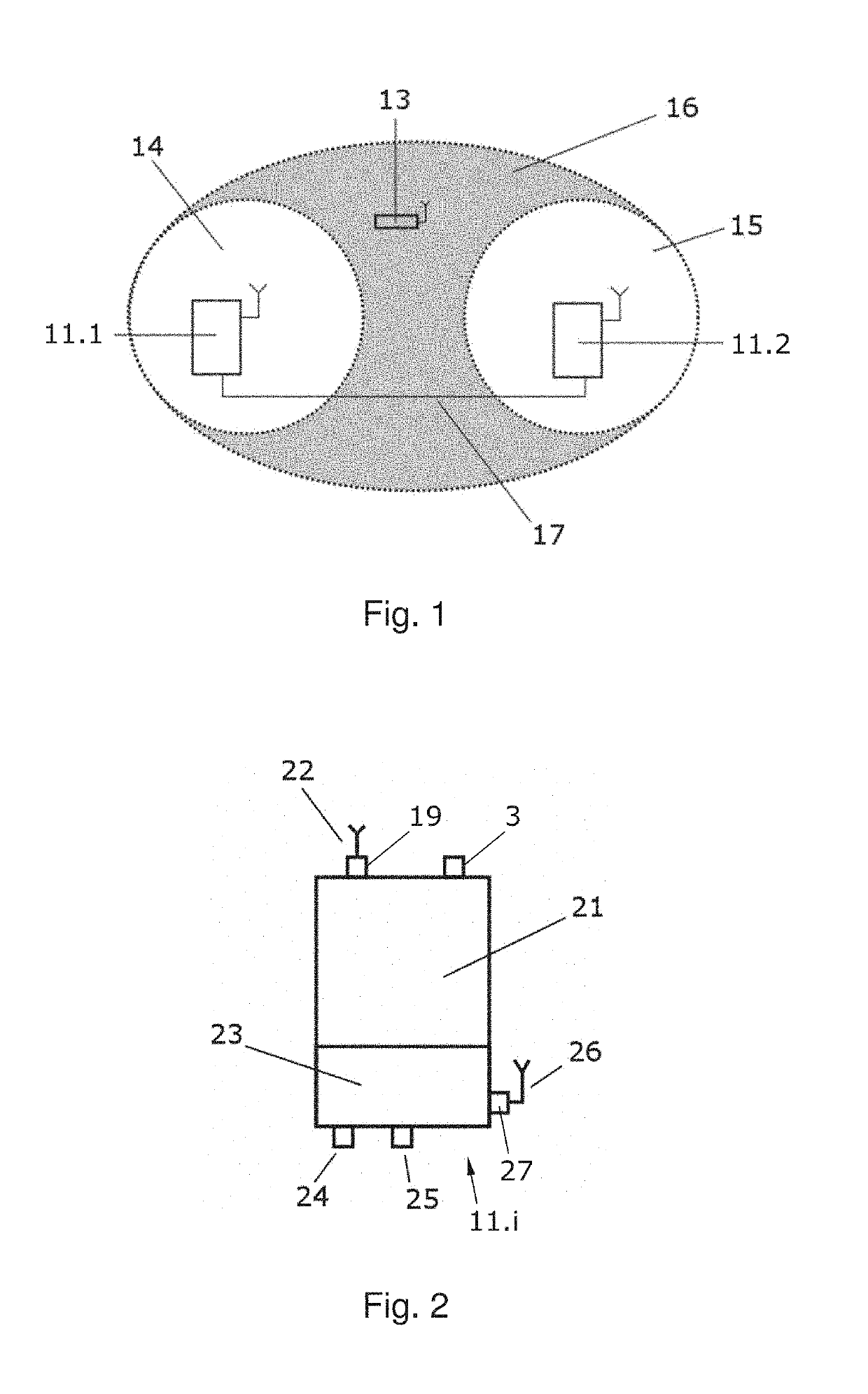
[0027]A schematic illustration of the added value of the invention is given in FIG. 1. UHF RFID reader unit 11.1 and UHF RFID reader unit 11.2 are shown, wherein white circle 14 and circle 15 depict the read ranges associated with the reader unit 11 and the reader unit 12, respectively.

[0028]A passive UHF RFID tag 13 is situated outside of the read range of both reader units, and thus, will the tag 13 not be read by the reader units. A grey section 16 illustrates the region where the addition of the powers supplied by reader unit 11.1 and the reader unit 11.2 is sufficient to power the tag 13. However, if both readers are independently trying to interrogate the tag by means of transmitting an interrogation signal, chances of a successful interrogation cycle are slim due to interference of the modulation of the interrogation signals, decrease of the modulation depth and mixing of the communication protocol followed by each reader. The present invention describes a solution for these ...


PUM


Abstract

A UHF RFID system is disclosed in which an RFID transponder or tag can be simultaneously powered and interrogated by multiple RFID transceivers. The architecture of the system is such that each transceiver generates its own carrier wave, with a frequency that might be equal to or different from the other units, and the interrogation data is distributed throughout a network of transceivers and modulated by each transceiver unit onto their own carrier waves. During an interrogation period, one or more of the transceivers will be configured as the master unit, generating and distributing the protocols commands. The other units can be configured as transmitters, receivers or transceivers. After each period the units may be given different roles. The proposed setup yields a system with the capability to power and interrogate RFID tags with multiple readers, without compromising the required modulation depth and protocol handling.

Description

[0001]This invention relates to a preferably Ultra High Frequency (UHF) radio frequency identification (RFID) system comprising multiple RFID reader units, in which the units can generate carrier waves which are modulated by interrogation data to be received by tags. More particularly the invention relates to a system of RFID reader units, comprising a plurality of reader units at least comprising a first reader unit provided with a transmitter for transmitting an electromagnetic interrogation signal comprising a carrier wave which is modulated with interrogation data for interrogating an RFID tag and at least one second reader unit provided with a transmitter for transmitting an electromagnetic interrogation signal comprising a carrier wave which is modulated with interrogation data for interrogating an RFID tag wherein the system is arranged to receive a reply signal generated by an RFID tag in response to a carrier wave modulated with an interrogation signal received by the tag.B...

Claims


Application Information

Patent Timeline
IPC IPC(8): G06K7/10
CPCG06K7/10366G06K7/10069G06K7/10079G06K7/10297
Inventor COMPAIJEN, PAUL JASPERVAN MEGEN, MAARTEN JACOBUS JOHANNESESSINK, BEREND HENDRIKVAN LAKWIJK, REINBRAND GERHARD JAAKOB FRANS OTTOKAR JOHANAN
Owner N V NETHERLANDSCHE APPNFAB NEDAP
Learn More