Watertight Slide Fastener

Active Publication Date: 2019-05-16
TAIWAN UNITED OUTDOOR GRP INC
View PDF5 Cites 38 Cited by
  • Summary
  • Abstract
  • Description
  • Claims
  • Application Information

AI Technical Summary

Benefits of technology

[0007]To solve the above problems, an objective of the present invention is to provide a watertight slide fastener

Problems solved by technology

Furthermore, after a period of time of repetitious use of the slide fastener 9, the resilient top end stop 93 made of soft material becomes worn due to rep

Method used


Image

  • Watertight Slide Fastener
  • Watertight Slide Fastener
  • Watertight Slide Fastener

Examples


Example

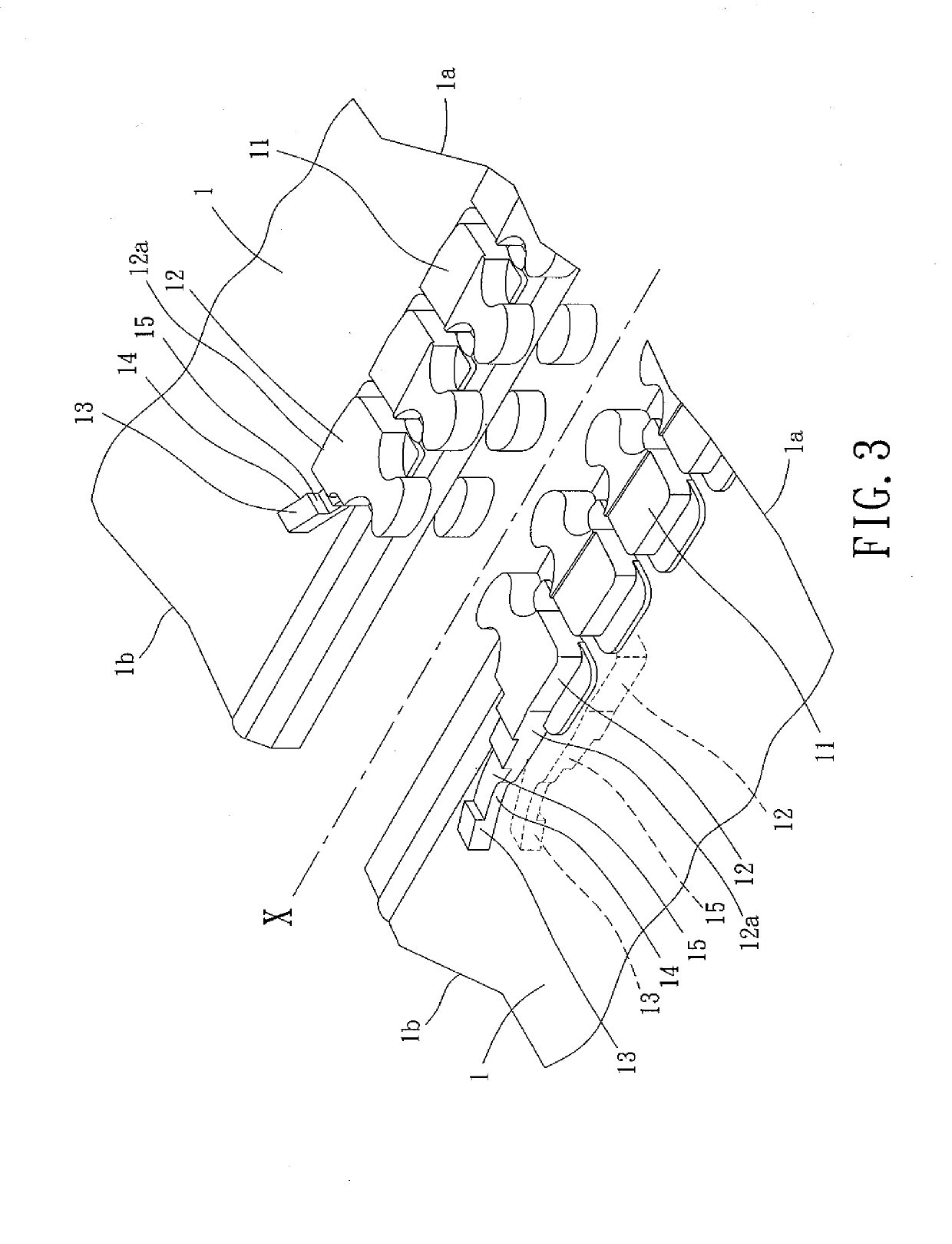
[0038]With reference to FIG. 4, a watertight slide fastener of a first embodiment according to the present invention includes two tapes 1, a top end stop 2, and a slider 3. Each of the two tapes 1 includes an inner edge on which a plurality of scoops 11 is mounted. The top end stop 2 is contiguous to the last one of the plurality of scoops 11. The slider 3 is configured to close or separate the scoops 11 and the top end stop 2.

[0039]FIG. 3 shows the structure of the two tapes 1. Each of the two tapes 1 includes a first end 1a and a second end 1b. Furthermore, each of the two tapes 1 includes a waterproof layer. As an example, the waterproof layer can be obtained by heating a thermoplastic resin which is then extruded or injected to envelop the two tapes 1 to provide the two tapes 1 with impermeability to liquid and water. Each of the inner edges of the two tapes 1 facing each other is provided with the plurality of scoops 11 and an upper stopper scoop 12. The plurality of scoops 11 ...

Example

[0048]FIGS. 9 and 10 show a watertight slide fastener of a second embodiment according to the present invention, which also includes two tapes 1, a top end stop 2, and a slider 3. Each of the two tapes 1 includes an inner edge on which a plurality of scoops 11 is mounted. The top end stop 2 is contiguous to the last one of the plurality of scoops 11. The slider 3 is configured to close or separate the scoops 11 and the top end stop 2. Each of the inner edges of the two tapes 1 facing each other is provided with the plurality of scoops 11 and an upper stopper scoop 12′. The plurality of scoops 11 on each of the two tapes 1 is consecutively disposed from the first end 1a towards the second end 1b. The upper stopper scoop 12′ on each of the two tapes 1 includes a first end contiguous to the last one of the plurality of scoops 11 on the respective one of the two tapes 1. The upper stopper scoop 12′ of each of the two tapes 1 includes a second end having an extension 13′. A thickness bet...

Example

[0050]FIGS. 11 and 12 show a watertight slide fastener of a third embodiment according to the present invention, which also includes two tapes 1, a top end stop 2, and a slider 3. Each of the two tapes 1 includes an inner edge on which a plurality of scoops 11 is mounted. The top end stop 2 is contiguous to the last one of the plurality of scoops 11. The slider 3 is configured to close or separate the scoops 11 and the top end stop 2. Each of the inner edges of the two tapes 1 facing each other is provided with the plurality of scoops 11 and an upper stopper scoop 12″. The plurality of scoops 11 on each of the two tapes 1 is consecutively disposed from the first end 1a towards the second end 1b. The upper stopper scoop 12″ on each of the two tapes 1 includes a first end contiguous to the last one of the plurality of scoops 11 on the respective one of the two tapes 1. The two upper stopper scoops 12″ have the same shape and structure as the plurality of scoops 11 to permit meshing of...


PUM


Abstract

A watertight slide fastener includes two tapes each having a waterproof layer. Each of the two tapes includes an inner edge on which a plurality of consecutively disposed scoops and an upper stopper scoop made of a rigid plastic are mounted. A first end of each upper stopper scoop is contiguous to the last one of the plurality of scoops. A second end of each upper stopper scoop has an extension. A top end stop is formed on upper and lower faces of each of the two tapes by an elastomer and envelops an upper face and a lower face of each extension. Each of two outer sides of the top end stop has a shoulder. A slider includes an upper body and a lower body interconnected to the upper body by a diamond. Each of two sides of the upper and lower bodies has a flange.

Description

CROSS REFERENCE TO RELATED APPLICATION[0001]The application claims the benefit of Taiwan application serial No. 106139187, filed on Nov. 13, 2017, and the entire contents of which are incorporated herein by reference.BACKGROUND OF THE INVENTION1. Field of the Invention[0002]The present invention relates to a watertight slide fastener and, more particularly, to a watertight slide fastener preventing leakage through a top end stop thereof.2. Description of the Related Art[0003]FIG. 1 shows a conventional slide fastener 8 including a pair of fastener tapes 81. Scoops 82 are disposed on two mutually facing edges of the fastener tapes 81. A resilient top end stop 83 is mounted on the fastener tapes 81 and is connected to the scoops 82. The resilient top end stop 83 includes an accommodating portion 84 in a central portion thereof for accommodating a diamond 86 of a slider 85. A protrusion 87 extends upright along a periphery of the resilient top end stop 83. A passage portion 88 is defin...

Claims


Application Information

Patent Timeline
IPC IPC(8): A44B19/32A44B19/26A44B19/34
CPCA44B19/32A44B19/26A44B19/34A44B19/301
Inventor CHENG, JUNG-YUAN
Owner TAIWAN UNITED OUTDOOR GRP INC
Why Eureka
Try Eureka