

Rotary encoder and rotary encoder manufacturing method
a technology of rotary encoder and manufacturing method, which is applied in the direction of optical conversion of sensor output, measurement apparatus components, instruments, etc., can solve the problem that users cannot check whether liquid has intruded into the insulating resin cover
- Summary
- Abstract
- Description
- Claims
- Application Information
AI Technical Summary
Benefits of technology
Problems solved by technology
Method used
Image

Examples
first embodiment
[Configuration of the Rotary Encoder]
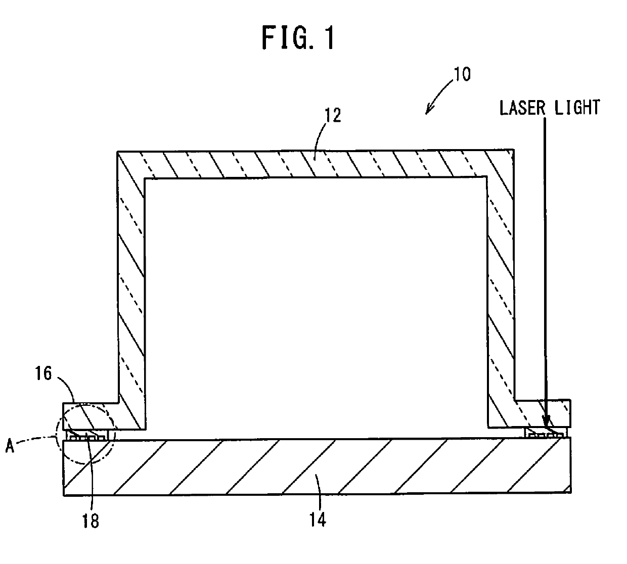
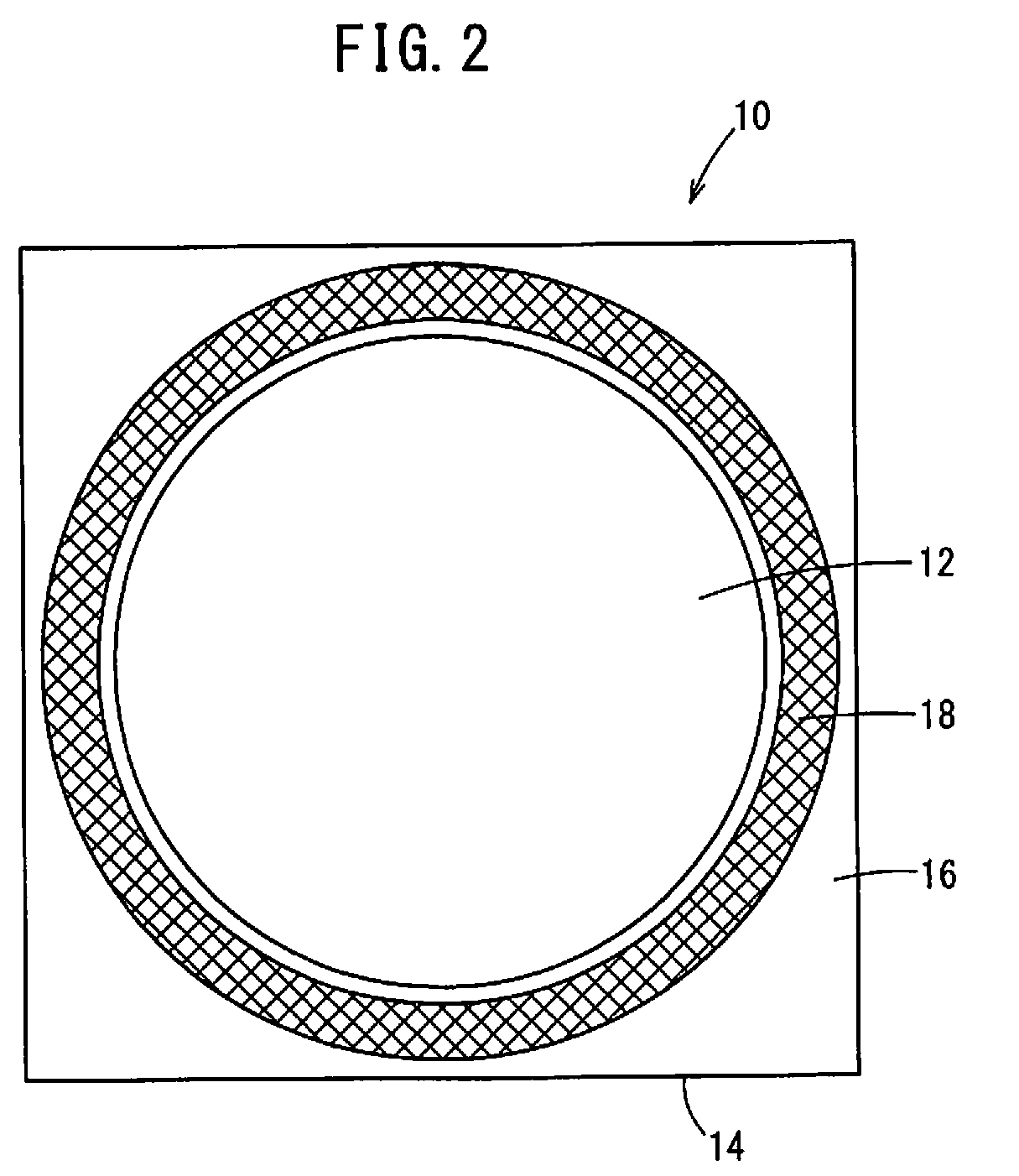
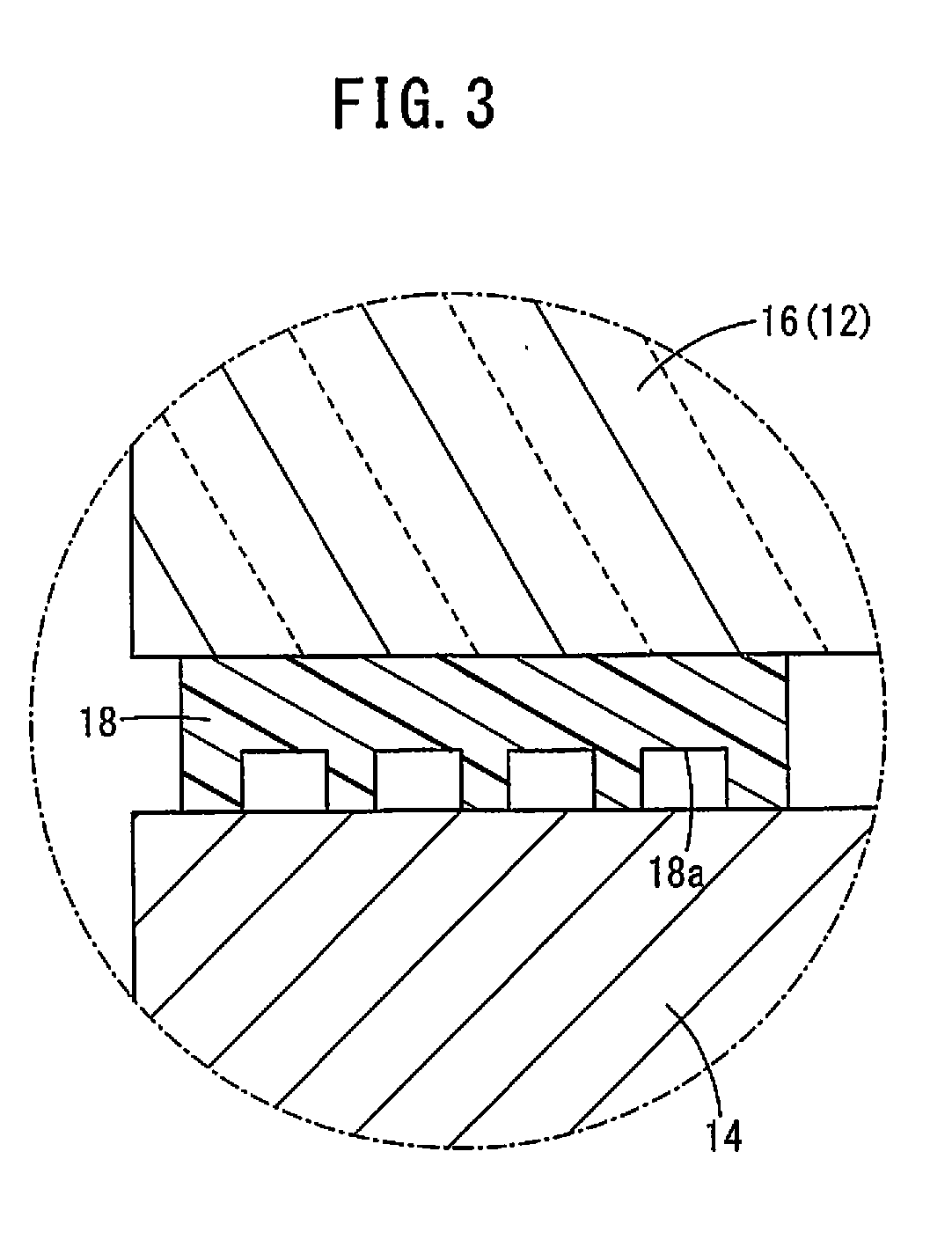
[0018]FIG. 1 is a schematic cross-sectional view of a rotary encoder 10. FIG. 2 is a schematic view of the rotary encoder 10 as seen from a cover 12 side. FIG. 3 is an enlarged view of the circle A portion of FIG. 1.
[0019]The rotary encoder 10 includes a housing 14 made of metal and a cover 12 made of a light transmissive resin. A rotating encoder board, a light emitting element, a light receiving element, and the like, which are not shown in the drawings, are housed within a space formed by the housing 14 and the cover 12.
[0020]Thermosetting resin 18 is provided on a surface of the cover 12 facing the housing 14, which is a flange portion 16. The thermosetting resin 18 is provided to have a ring shape (see FIG. 2) when the rotary encoder 10 is viewed from the cover 12 side. The thermosetting resin 18 is formed integrally with the cover 12 when the cover 12 is formed using injection molding.
[0021]In a state where the cover 12 is assembled with th...
second embodiment
[Configuration of Rotary Encoder]
[0027]FIG. 4 is a schematic cross-sectional view of the rotary encoder 10. FIG. 5 is a schematic view of the rotary encoder 10 as seen from the cover 12 side. FIG. 6 is an enlarged view of the circle B portion of FIG. 4. In the second embodiment, the arrangement of the thermosetting resin 18 is different from in the first embodiment. In the following, configurations that are the same as in the first embodiment are given the same reference numerals, and descriptions thereof are omitted.
[0028]The thermosetting resin 18 is provided on the surface of the cover 12 facing the housing 14, which is the flange portion 16. The thermosetting resin 18 is provided to have a double-layered ring shape (see FIG. 5) including thermosetting resin 18b on an outer circumferential side and thermosetting resin 18c on an inner circumferential side, when the rotary encoder 10 is viewed from the cover 12 side. In this way, two layers of seals are provided from the outer side...
third embodiment
[0031]FIG. 7 is a schematic cross-sectional view of the rotary encoder 10. In the third embodiment, the arrangement of the thermosetting resin 18 is different from in the first embodiment. In the following, configurations that are the same as in the first embodiment are given the same reference numerals, and descriptions thereof are omitted.
[0032]A groove portion 20 with a ring shape is formed in a surface of the housing 14 where the cover 12 is attached. A convex portion 22 with a ring shape that engages with the groove portion 20 of the housing 14 is formed on the flange portion 16 of the cover 12.
[0033]The thermosetting resin 18 is formed integrally with the cover 12 through injection molding, and is provided on the surface of the flange portion 16 of the cover 12 facing the housing 14 and on the side surface of the convex portion 22. In a state where the cover 12 is assembled with the housing 14, the thermosetting resin 18 is irradiated with laser light from the cover 12 side, t...
PUM
 Abstract
Description
Claims
Application Information