Otoscope Providing Multi-Directional Illumination

a multi-directional, otoscope technology, applied in the field of otoscopes, can solve the problem of limiting the depth of insertion of the speculum, and achieve the effect of improving the viewing of the ear structur

a multi-directional, otoscope technology, applied in the field of otoscopes, can solve the problem of limiting the depth of insertion of the speculum, and achieve the effect of improving the viewing of the ear structur

US20190209001A1Active Publication Date: 2019-07-11WISCONSIN ALUMNI RES FOUND

Image

  • Otoscope Providing Multi-Directional Illumination
  • Otoscope Providing Multi-Directional Illumination
  • Otoscope Providing Multi-Directional Illumination

Examples


Embodiment Construction

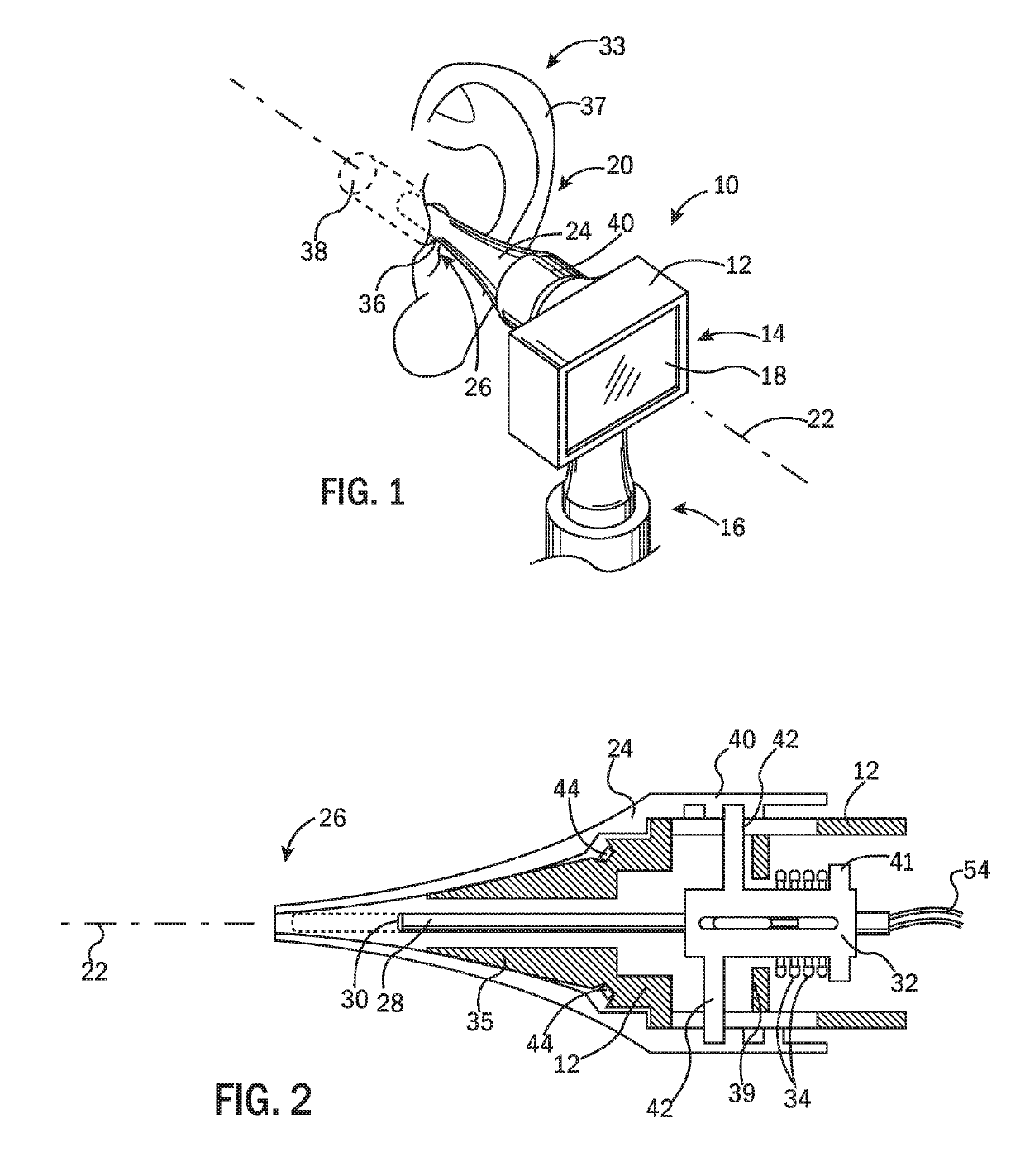
[0045]Referring now to FIG. 1, an otoscope 10 of the present invention may provide a housing 12 having a head portion 14 and a detachable grip portion 16. The grip portion 16 is sized to be grasped by the hand of a healthcare professional in the manner of a conventional otoscope with the grip portion 16 extending generally upward from the healthcare professional's hand to the head portion 14.

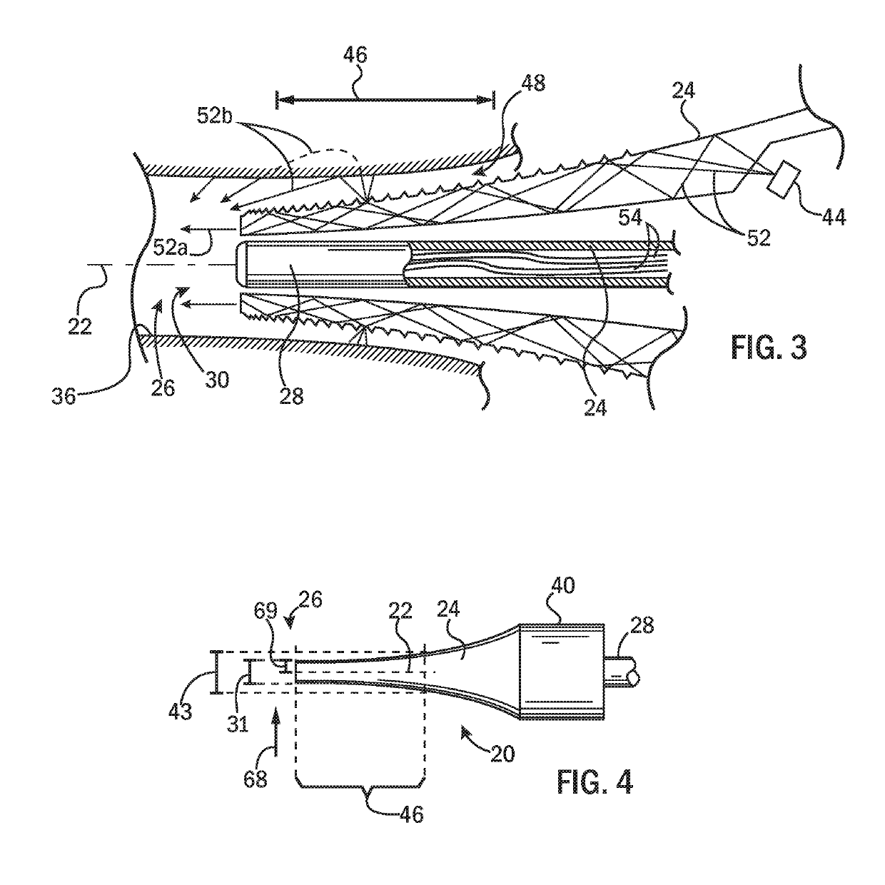
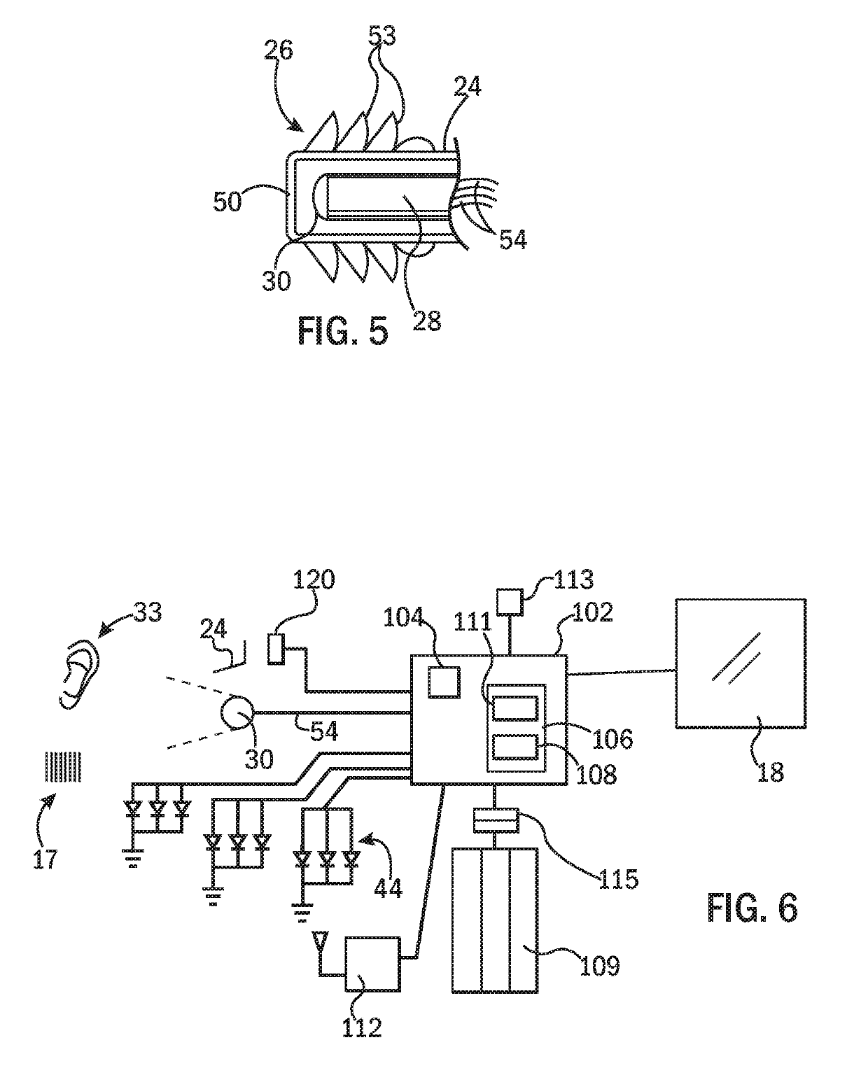
[0046]A front surface of the head portion 14 may provide for an electronic display 18, for example, being a backlit three-color liquid crystal display (LCD) of a type known in the art. An elongate probe assembly 20 may extend from a rear face of the head portion 14 in a direction away from the display 18 along an axis 22 normal to the surface of the display 18. The probe assembly 20 may include a generally conical sheath 24 constructed at least in part of the transparent thermoplastic material to provide for light conducting properties as will be described below.

[0047]As is generally understood,...


PUM


Abstract

An otoscope provides a disposable speculum sleeve that conducts light to a narrow tip holding an electronic camera. By removing the light source from the tip, the diameter of the tip may be further reduced to allow the space of the ear canal to be shared between the otoscope and a tool such as a curette for removing foreign objects or to permit the tip to navigate around ear obstructions. The sleeve may provide for multidirectional illumination of the ear structure for improved visualization. The tip and sleeve may be flexible for increased patient comfort when using a compact tip design.

Description

CROSS REFERENCE TO RELATED APPLICATION[0001]This application is a continuation of U.S. patent application Ser. No. 14 / 749,945, filed Jun. 25, 2015, hereby incorporated by reference.BACKGROUND OF THE INVENTION[0002]The present invention relates to an otoscope for inspection of the ear and in particular to an otoscope employing an electronic camera insertable into the ear canal.[0003]An otoscope is a medical device allowing a healthcare professional to inspect the ear canal and tympanic membrane (eardrum). A simple otoscope provides for a hollow funnel-shaped speculum whose small end is inserted into the ear canal. The funnel shape of the speculum stabilizes the otoscope against the ear canal wall and may limit the depth of insertion of the speculum. Modern otoscopes include an internal source of illumination directed down the speculum axis from a contained battery-operated lamp and may provide a magnifying lens supported outside the ear and aligned with the axis of the speculum to pr...

Claims


Application Information

Patent Timeline
11 Jul 2019
Publication
US20190209001A1
IPC
A61B1/227; A61B1/00; A61B1/05; A61B1/07; A61B1/06
CPC
A61B1/227; A61B1/00142; A61B1/00135; A61B1/05; A61B1/07; A61B1/0615; A61B1/00103
Inventors
BERBEE, JAMES; HAMEDANI, AZITA