This helps you quickly interpret patents by identifying the three key elements:
Problems solved by technology
Method used
Benefits of technology
[0035] The cable supports multiple conductors and a KEVLAR core in a foam filled jacket that prevents moisture transmission to the camera. A moisture-activated filler included in the cable jacket self-heals the jacket against punctures and abrasions. Hydrodynamic vanes can be attached to the cable jacket and/or the cable jacket can be constructed to facilitate cable movement with minimal lift at the camera.
[0036] The camera is packaged in a rubber housing that contains a potting and desiccant material. The camera housing containing the camera electronics may be purged with a rare earth gas. A number of lights are concentrically mounted within and/or around the camera housing,
Problems solved by technology
This equipment is very costly and is typically used by oil companies, archaeologists, researchers and salvage operators.
Consequently, operating performance can suffer from an inability to maintain a known and constant attitude and orientation of the camera to a support watercraft.
Ref
Method used
Image
Click on the blue label to locate the original text in one second.
Reading with bidirectional positioning of images and text.
Examples
Embodiment Construction
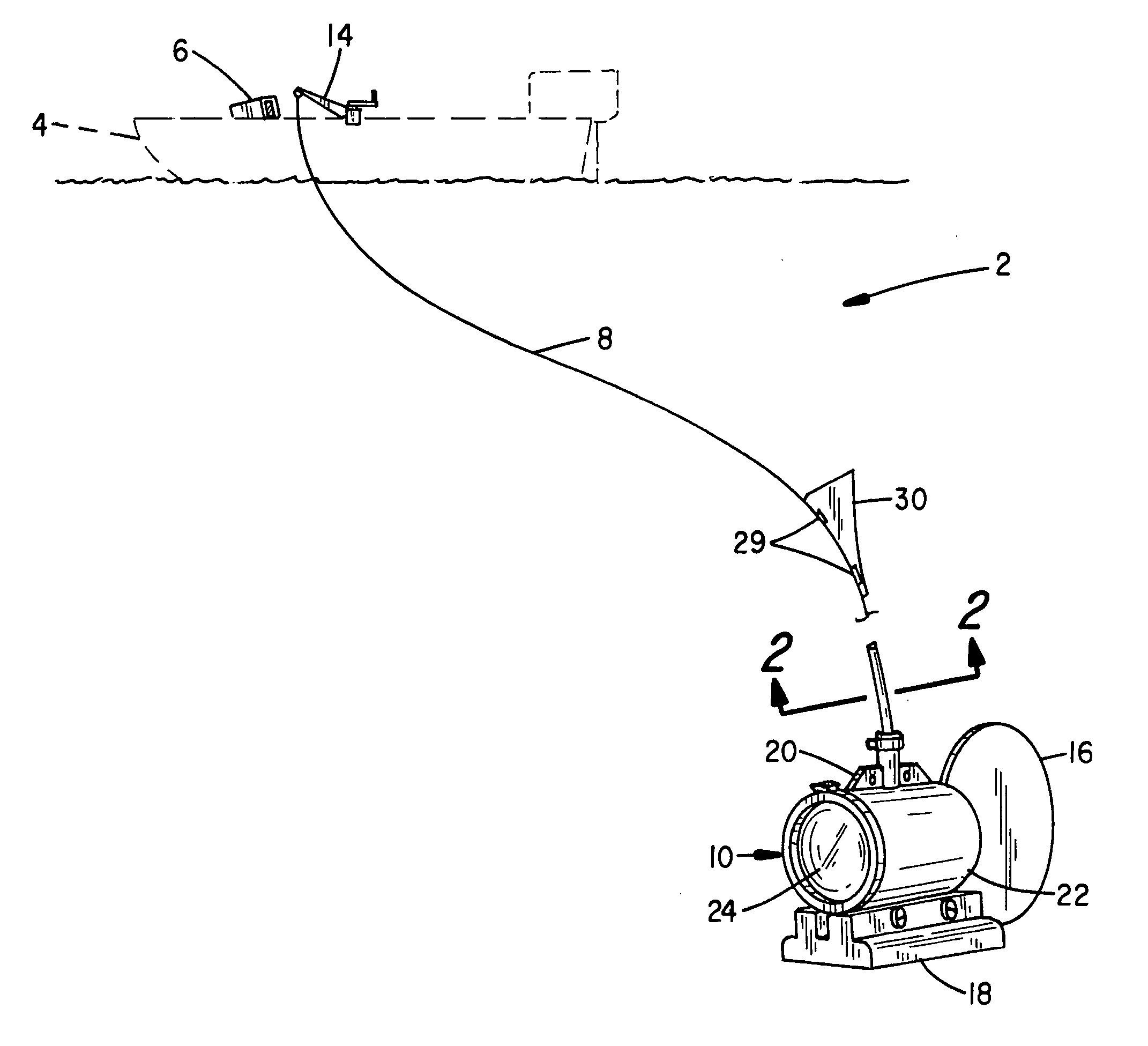
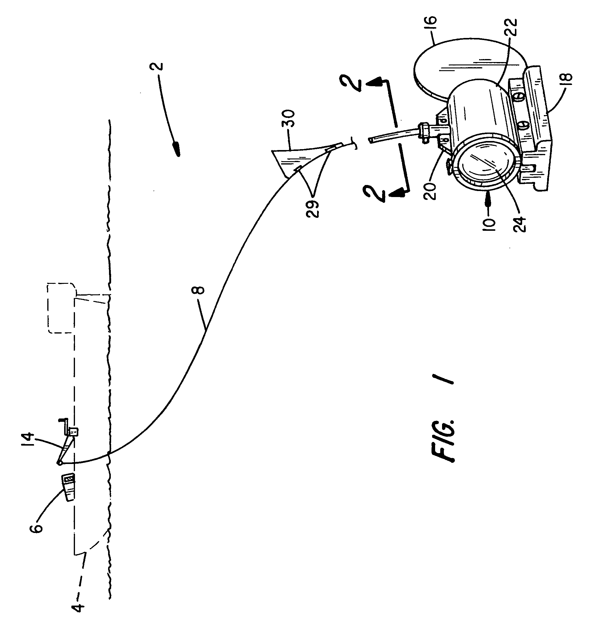
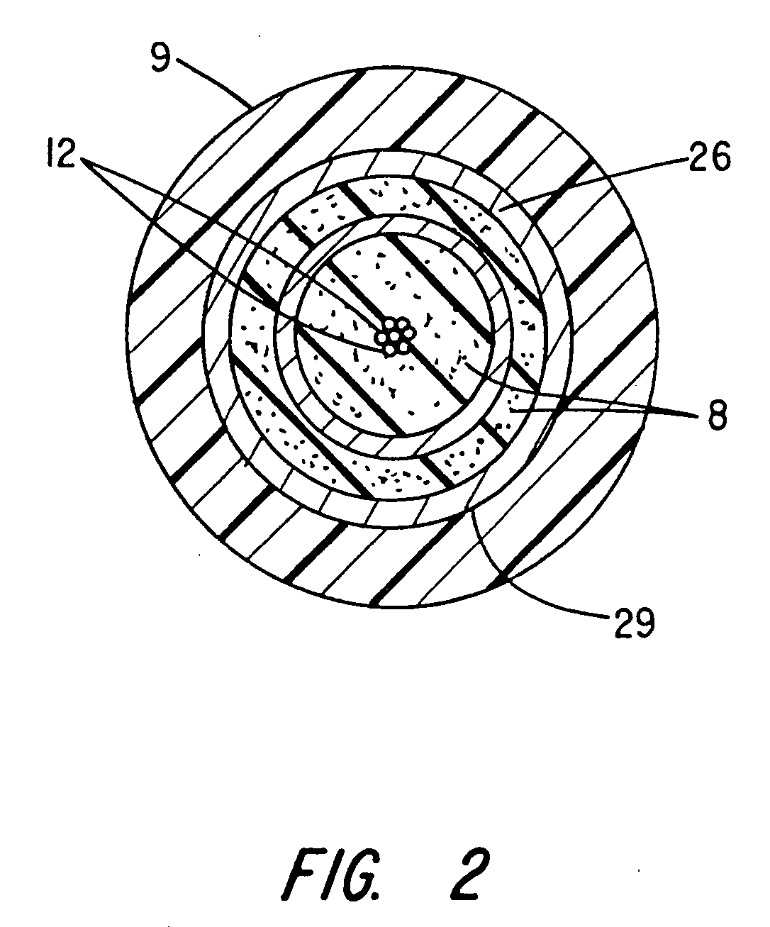
[0080] Referring to FIG. 1, a submersible video viewing system 2 is shown as it appears when configured for operation from a watercraft or boat 4. A viewing monitor 6 is supported at the boat 4 and a coaxial cable 8 is tethered to a submerged camera 10. A pair of conductors 12, reference FIG. 2, supply power and / or control signals to the camera 10. Additional conductors may be included in the cable 8.
[0081] Video, audio and / or other control and / or sensed signals are transmitted over the conductors 12 between the camera 10, the monitor 6 and associated control circuitry. A boat operator is thereby able to visually monitor the presence of fish, submerged objects or any condition capable of being detected and reported by associated sensors. The viewing range will depend on water clarity, depth and light conditions, among other factors. Surface turbulence, drag and tracking at the camera 10 may also affect viewing. Other physical parameters may also be monitored by the camera 10 and as...
PUM
Abstract
A modular, portable, submersible video viewing system. The system includes a viewing monitor, camera and interconnecting multi-conductor cable that store and deploy for underwater viewing. Webs at the camera housing interconnect to cable clips, bottom support plates, a swivel coupler or steering guide and/or pole to control camera orientation. Alternative rudders and/or hydrodynamic ballast weights (with or without a keel) mount to the webs to control camera tracking when towed. A fish-shaped camera is also disclosed. Alternative stationary supports permit directed or “pan” viewing. A multi-aperture reflection suppressor and etched lens mount to the camera and cooperate with an array of LED's to direct light relative to the viewing field of the camera lens. Various sunshields, lights and/or lenses and filters are optionally mountable to the monitor and camera. Alternative monitor housings are disclosed that contain the viewing monitor, battery and attendant control circuitry and camera. Handles, cable wraps, integral and detachable sunshields, and manual and remote motorized cable take-up spools are also disclosed. Video storage/re-play, combinations of switched multi-frequency lights and display modes of depth and temperature at camera, camera direction and water depth are also included.
Description
RELATED APPLICATION DATA [0001] This is a continuation-in-part of application Ser. No. 10 / 287,245, filed Nov 4, 2002; which is a continuation-in-part of application Ser. No. 09 / 907,278, filed Jul. 17, 2001, now U.S. Pat. No. 6,476,853; which is a continuation of application Ser. No. 09 / 611,261, now U.S. Pat. No. 6,262,761; which is a continuation-in-part of application Ser. No. 09 / 186,593, now U.S. Pat. No. 6,097,424; application Ser. No. 29 / 119,957, now Pat. No. D438,881; and application Ser. No. 29 / 116,362, now Pat. No. D439,589; and application Ser. No. 29 / 165,884, filed Aug. 19, 2002 now Pat. No. D489,387.BACKGROUND OF THE INVENTION [0002] The present invention relates to portable underwater viewing systems and, in particular, a number of alternative systems including camera assemblies with improved camera tracking and enhanced light distribution and portable monitor housings with improved cable take-up capabilities, re-playable viewing and detachable sunshields. [0003] Varietie...
Claims
Application Information
Patent Timeline
Application Date:The date an application was filed.
Publication Date:The date a patent or application was officially published.
First Publication Date:The earliest publication date of a patent with the same application number.
Issue Date:Publication date of the patent grant document.
PCT Entry Date:The Entry date of PCT National Phase.
Estimated Expiry Date:The statutory expiry date of a patent right according to the Patent Law, and it is the longest term of protection that the patent right can achieve without the termination of the patent right due to other reasons(Term extension factor has been taken into account ).
Invalid Date:Actual expiry date is based on effective date or publication date of legal transaction data of invalid patent.