Inflator devices having a moisture barrier member

a technology of moisture barrier and inflator, which is applied in the direction of positive displacement liquid engine, pedestrian/occupant safety arrangement, and valve construction, etc. it can solve the problems of affecting the efficiency of inflator devices, and prior art generally failing to provide inflator devices, etc., to achieve simple, efficient and cost effective, increase or improve simplicity, efficiency and cost effectiveness

Inactive Publication Date: 2005-06-09
AUTOLIV ASP INC
View PDF40 Cites 20 Cited by
  • Summary
  • Abstract
  • Description
  • Claims
  • Application Information

AI Technical Summary

Benefits of technology

[0008] The general object of the invention can be attained, at least in part, through an improvement in an inflator device that includes a housing defining a storage chamber. A supply of gas generant material is disposed within the storage chamber and an initiator assembly is joined to the housing. The initiator assembly includes an initiator in actuating communication with the supply of gas generant material. In accordance with certain preferred embodiments, the invention involves the improvement of a moisture barrier member that is disposed between the initiator assembly and the supply of gas generant material. The moisture barrier member prevents moisture transmission from the initiator assembly to the supply of gas generant material. The moisture barrier member, however, ruptures upon actuation of the initiator.
[0009] The prior art generally fails to provide inflator devices wherein moisture transmission to a supply of gas generant material contained there within can desirably be reduced, minimized or otherwise prevented or avoided in a manner which is as simply, efficient and cost effective as may otherwise be desired. In particular, the prior art generally fails to provide inflator devices wherein moisture transmission from an initiator assembly, such as at least in part formed from a thermoplastic material, to a supply of moisture sensitive gas generant material there within contained, is desirably reduced, minimized or otherwise prevented or avoided in a manner which is one or more of increased or improved simplicity, efficiency and cost effectiveness.
[0010] The invention further comprehends an inflator device that includes a housing defining a storage chamber having an inner surface. A supply of gas generant material is disposed within the storage chamber and an initiator assembly is joined to the housing. The initiator assembly includes an initiator in actuating communication with the supply of gas generant material. In accordance with one preferred embodiment of the invention, a specified non-planar moisture barrier member is disposed between the initiator assembly and the supply of gas generant material. The non-planar moisture barrier member includes a base portion having a first surface facing the initiator assembly and a second surface on a side opposite the first surface and facing the supply of gas generant material. An outer edge of the moisture barrier member is adjacent the storage chamber inner surface and a sleeve extends from the moisture barrier member outer edge. The moisture barrier member includes a cup portion extending from the base portion second surface. The non-planar moisture barrier member is disposed adjacent the initiator assembly and the cup portion is in covering relation with at least a portion of the initiator. The non-planar moisture barrier member prevents moisture transmission from the initiator assembly to the supply of gas generant material. Upon actuation of the initiator, the non-planar moisture barrier member ruptures.
[0011] The invention still further comprehends an inflator device including a housing defining a storage chamber having an inner surface. A baffle is at least partially disposed within the storage chamber. The baffle includes a passageway and a plurality of exit holes. A supply of gas generant material is disposed within the storage chamber and outside the baffle passageway. An initiator assembly is joined to the housing. The initiator assembly includes an initiator in actuating communication with the supply of gas generant material, with the initiator at least in part contained within the baffle passageway. A non-planar moisture barrier member is disposed between the initiator assembly and the supply of gas generant material. The non-planar moisture barrier member includes a base portion having a first surface facing the initiator assembly and a second surface on a side opposite the first surface and facing the supply of gas generant material. An outer edge of the moisture barrier member is adjacent the housing inner surface and a sleeve extends from the moisture barrier member outer edge. The moisture barrier member includes a cup portion extending from the base portion second surface. The non-planar moisture barrier member is disposed adjacent the initiator assembly with the cup portion in covering relation with at least a portion of the initiator, and at least a portion of the cup portion disposed between the initiator and an inside surface of the baffle. The non-planar moisture barrier member prevents moisture transmission from the initiator assembly to the supply of gas generant material. Upon actuation of the initiator, the cup portion of the non-planar moisture barrier member ruptures.

Problems solved by technology

The moisture barrier member, however, ruptures upon actuation of the initiator.
The prior art generally fails to provide inflator devices wherein moisture transmission to a supply of gas generant material contained there within can desirably be reduced, minimized or otherwise prevented or avoided in a manner which is as simply, efficient and cost effective as may otherwise be desired.
In particular, the prior art generally fails to provide inflator devices wherein moisture transmission from an initiator assembly, such as at least in part formed from a thermoplastic material, to a supply of moisture sensitive gas generant material there within contained, is desirably reduced, minimized or otherwise prevented or avoided in a manner which is one or more of increased or improved simplicity, efficiency and cost effectiveness.

Method used


Image

  • Inflator devices having a moisture barrier member
  • Inflator devices having a moisture barrier member
  • Inflator devices having a moisture barrier member

Examples


Embodiment Construction

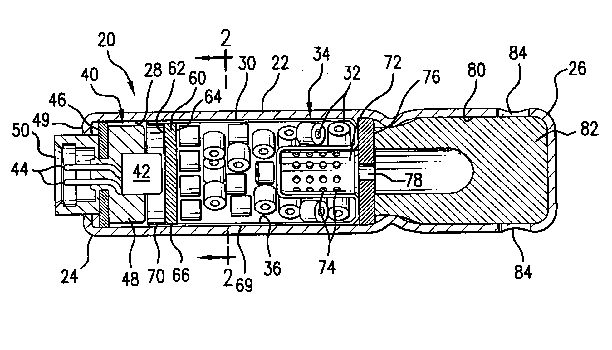
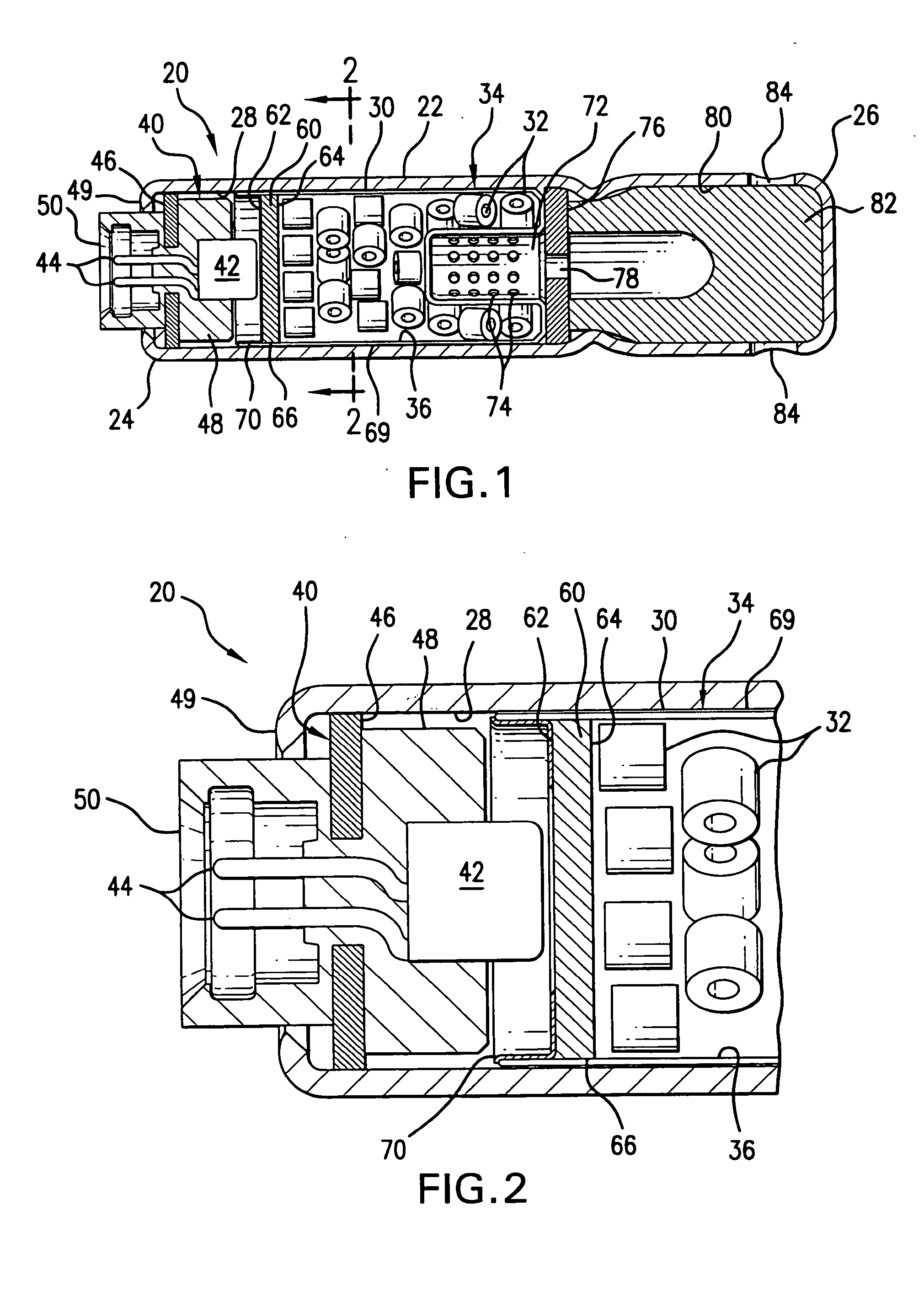
[0018] The present invention provides an improved inflator device such as to desirably reduce, minimize and / or avoid moisture communication there within, such as from an initiator assembly into a storage chamber that contains a supply of gas generant material.

[0019] As will be described in greater detail below, the present invention more particularly provides an inflator device having a moisture barrier member, such as disposed between a thermoplastic molded adaptor of an initiator assembly and a storage chamber containing a supply of moisture sensitive gas generant material, for example.

[0020] An inflator device 20 according to one embodiment of the invention is shown in FIG. 1. An enlarged view of a portion of the inflator device 20 of FIG. 1, taken along line 2-2, is shown in FIG. 2. The inflator device 20 includes a housing 22 having a first end 24 and a second end 26 opposite the first end 24. The housing 22 shown in FIG. 1 is generally tubular in shape and an inner surface 2...


PUM


Abstract

An inflator device including a housing defining a storage chamber and a supply of gas generant material disposed within the storage chamber. The inflator device includes an initiator assembly having an initiator in actuating communication with the supply of gas generant material. A moisture barrier member is disposed between the initiator assembly and the supply of gas generant material. The moisture barrier member acts to prevent moisture transmission from the initiator assembly to the supply of gas generant material. Upon actuation of the initiator, however, the moisture barrier member ruptures to permit reaction initiating communication between the initiator and at least a portion of the supply of gas generant material contained within the inflator device.

Description

BACKGROUND OF THE INVENTION [0001] This invention relates generally to inflator devices such as used in vehicular safety restraint installations and, more particularly, to inflator devices such as desirably reduce, minimize and / or avoid moisture communication to moisture sensitive contents thereof. [0002] Inflator devices such as used in vehicular safety restraint installations commonly employ gas generant materials which, upon actuation by an initiator device, desirably react or otherwise produce or form gas, such as may be used to inflate an inflatable airbag cushion or bag. Such gas generant materials are commonly formed as a tablet or other gas generant body having a predetermined shape and size. As will be appreciated, the selected shape and size of a gas generant material body can desirably be varied to provide a particular surface area, as the surface of a gas generant body can provide a convenient means of control over the rate of production of gas upon reaction of the gas g...

Claims


Application Information

Patent Timeline
Patent Type & Authority Applications(United States)
IPC IPC(8): B60R21/264F04B19/24F04B39/00
CPCB60R21/2644B60R21/16B60R21/261F04B19/24
Inventor CLARK, MARCUSSMITH, BRADLEY W.LARSEN, ALAN R.
Owner AUTOLIV ASP INC
Why Eureka
Try Eureka