Method for preparation of metallic and ceramic foam products and products made

a technology of ceramic foam and products, applied in the field of method for preparation of metallic and ceramic foam products and products, can solve the problems of low efficiency, difficult control of pore size or orientation using these known techniques, and beneficial effects of new manufacturing approaches on performance and cost, and achieves improved mechanical properties and energy absorption capacity, improved efficiency, and cost-effective

Inactive Publication Date: 2005-02-08
ADVANCED CERAMICS
View PDF26 Cites 81 Cited by
  • Summary
  • Abstract
  • Description
  • Claims
  • Application Information

AI Technical Summary

Benefits of technology

The present invention overcomes the problems encountered with conventional methods and compositions by providing efficient, cost-effective processes for preparing complex metallic, ceramic and cermet foam components with optimized dynamic mechanical properties. More specifically, the invention provides methods and compositions for metallic, ceramic and cermet foam components. In particular, the present invention relates to the freeform fabrication of metallic, ceramic, and cermet foams to form parts having complex geometries and that demonstrate superior mechanical properties and energy absorbing capacity.
Further, the present invention provides cost-effective methods of producing ultra-lightweight structures directly from CAD designs and offers the ability to manufacture complicated shape prototypes with minimal post-processing steps. In addition, the present invention provides methods and compositions for forming foam structures that have both open and closed cell porosity. The porous nature of the structures enhances their energy absorbing and blast amelioration capability and other mechanical properties such as compressive strength.
Accordingly, an object of the present invention is to fabricate metallic, ceramic, and cermet foam components with optimized mechanical properties in an efficient, cost-effective manner.

Problems solved by technology

Novel manufacturing approaches have beneficially affected performance and cost.
It is very difficult to control pore size or orientation using these known techniques.
Again, this process has little control of the pore size or orientation.
Furthermore, this method can be cost-prohibitive if used to create geometrically complex parts due to the molds required.
However, this process, referred to as the GASAR process, involves the use of molten metals and the injection of gases, and is therefore, technically complex and expensive.
Furthermore, the GASAR process allows the use of only one pore or cell orientation in a component and the shapes of the components are generally limited to plates, rods, and tubes.
Methods of making ceramic foams and cermet foams, which contain both metallic and ceramic materials, encounter similar difficulties.
Such methods are extremely complex and do not produce products with predictable quality or predictable porosity.
Further, prior cermet foams utilize a foaming agent, and thus both the shape and the amount of porosity can not be controlled.
As a result, it is difficult to make foams that have consistent mechanical properties.
Additionally, the manufacture of complex shaped foams using those methods is not feasible.
While others have developed processes for the fabrication of metallic foam structures with oriented porosity, none of those processes are capable of creating a combination of open and closed cell porosity, nor are they capable of creating components directly from CAD designs.
Additionally, control of pore size and pore orientation is difficult.
Moreover, conventional processes do not provide for the fabrication of integral structures with a metallic foam skin in a cost-effective manner.

Method used


Image

  • Method for preparation of metallic and ceramic foam products and products made
  • Method for preparation of metallic and ceramic foam products and products made
  • Method for preparation of metallic and ceramic foam products and products made

Examples


example 1

This example illustrates a blend formulation that can be used to make metallic foam. As shown in Table I, aluminum powder was blended with copper powder to produce an Al-4 wt % Cu alloy blend. The copper powder was added to the aluminum powder to create an alloy composition that would be more readily sinterable than pure aluminum alone. The aluminum and copper powders were similar in size. The Al and Cu powders were approximately 45 μm size particles, with an average particle size of 10 μm. The polymer (water-soluble) is a multi-component mixture. It was first melted in a Brabender high-shear mixer and the aluminum-copper powder mixture was then added as carefully as possible.

TABLE IBatch Size (cc):42Batch Temperature (C.):150Batch Speed (rpm):60DensityWeight (W)Volume (V)ActualActualg / cc%%VW (g)Aluminum2.70295.50.54222.7861.54Copper8.964.50.0080.322.90PMMA1.140.45018.9021.94Total1001.00042.0086.38

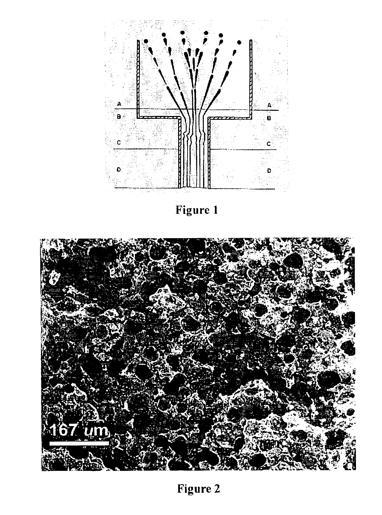
After compressing the composite blend into feed rods, they were extruded at temperatur...

example 2

This example illustrates another blend formulation that can be used to make metallic foam. As shown in Table III, aluminum was used as the primary metallic powder with small amounts of Mg and Sn added to the aluminum in an effort to reduce oxide layers formation on the metallic powder. In this example, the composite blend contained 8 wt % of Mg and 8 wt % of Sn. Additionally, Mg and Sn form a eutectic alloy with Al well below the maximum binder burnout temperature, thus allowing the foam material sufficient structural rigidity to be handled between the binder burnout and sintering steps.

This formulation used the polymethylmethacrylate (PMMA) as the polymer binder. Although PMMA has a relatively high viscosity, it was used as the polymer binder because it has clean burn-off characteristics. In this example, the xylene also served to reduce the viscosity of the PMMA.

TABLE IIIMaterialDensity (gm / cc)Volume %Weight %Weight (gm)Al2.70243.7567.149.65Sn7.311.256.24.6053Mg1.7385.004.73.46731...

example 3

Metallic foam components were made using the formulation in Table IV. The major binder phase was PMMA and the minor binder phase was butyl oleate. The same general procedure as in the previous examples was used with this formulation.

TABLE IVMaterialDensity (gm / cc)Volume %Weight %Weight (gm)Al2.70243.7562.649.65Sn7.311.254.843.84Mg1.7385.004.603.65PMMA1.140.0023.2918.48Al 3 wax0.925.002.431.93Butyl Oleate0.8555.002.271.8Totals100.00100%79.35

Further, this formulation permitted the use of enhanced extrusion forces and the use of a smaller extrusion tip with a 0.016″ extrusion nozzle. Prior to extrusion, the feedrods were heat treated at 100° C. for 2 hours. This formulation was successfully extruded at 170° C. and 275-300% flow. This formulation and extrusion conditions provided a smoother surface finish after extrusion.

The burnout schedule, shown below in Table V, was used for this formulation. The hold times listed in Table V can be adjusted in proportion to the dimensions of the sam...


PUM

PropertyMeasurementUnit
densityaaaaaaaaaa
particle sizesaaaaaaaaaa

Abstract

The present invention relates to the fabrication of low cost, in situ, porous metallic, ceramic and cermet foam structures having improved mechanical properties such as energy absorption and specific stiffness. Methods of fabricating the structures from compositions including ceramic and / or metallic powders are provided. The flowable compositions also include an immiscible phase that results in pores within the final structure. Furthermore, the structures may be shaped to have external porosity, such as with mesh-like structures.

Description

FIELD OF THE INVENTIONThe present invention relates to the fabrication of low cost, in situ, metallic foam components having oriented microstructures and improved mechanical properties such as energy absorption and specific stiffness. The present invention also relates to the fabrication of low cost, in situ, ceramic and, cermet foam components with improved mechanical properties.BACKGROUND OF INVENTIONCellular materials have been available for decades, but new opportunities for cellular materials are emerging. Novel manufacturing approaches have beneficially affected performance and cost. Additionally, higher levels of basic understanding about mechanical, thermal and acoustic properties have been developed. These provide an integrated pathway between manufacturing and design.Cellular materials have high stiffness and yield strength at low density relative to other competing materials and systems. That is, the cellular materials may be laminated between opposed sheets of another ma...

Claims


Application Information

Patent Timeline
Patent Type & Authority Patents(United States)
IPC IPC(8): B22F3/11B22F1/00B22F3/00B22F3/10C04B35/584C04B35/636C04B35/638C04B35/634C04B35/565C04B35/63C04B38/06B22F1/10B22F3/22
CPCB22F1/0059B22F3/008B22F3/1021B22F3/1103B22F3/1121B22F3/227C04B35/565C04B35/584C04B35/63424C04B35/63432C04B35/6365C04B35/638C04B38/065C04B38/067B22F1/0077B22F3/22B22F7/002C04B38/0051C04B38/0054C04B38/0058C04B38/0061C04B38/069C04B40/0028C04B2235/94B22F2003/1042B22F2003/1106B22F2998/00B22F2998/10B22F2999/00C04B2111/00129C04B2235/6021C04B2235/6022C04B2235/6026B22F2201/02B22F2201/013B33Y80/00B33Y70/00B33Y10/00Y02P10/25B22F1/108B22F1/10B22F10/38B22F10/18
Inventor ARTZ, GREGORYVAIDYANATHAN, K. RANJIFULCHER, MICHAEL L.RIGALI, MARK J.LOMBARDI, JOHN L.WALISH, JOSEPHCIPRIANI, RONALD A.
Owner ADVANCED CERAMICS
Why Eureka
Try Eureka