Jar lid opener

Inactive Publication Date: 2019-09-12
KLEIN MARC
6 Cites 1 Cited by

AI-Extracted Technical Summary

Problems solved by technology

Further, releasing the initial seal on the jar is typically a difficult task.
The jar's lid can be sealed quite tight and typically it is difficult for many...

Abstract

A jar lid opener that includes: a base; a first brace attached to the base; a second brace attached to the base, where the first brace abuts the second brace on the base; an opening formed between the first brace and second brace, wherein the opening is adapted to receive a jar lid; and a means to securely brace the jar lid on the first brace. The means to securely brace the jar lid preferably includes a pair of serrated blades. In one particular embodiment, the base forms a semi-circle and an angle forms between the first brace and second brace.

Application Domain

Threaded caps removal

Technology Topic

Biomedical engineeringSEMI-CIRCLE

Image

  • Jar lid opener
  • Jar lid opener
  • Jar lid opener

Examples

  • Experimental program(1)

Example

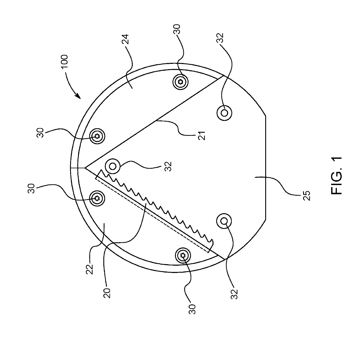
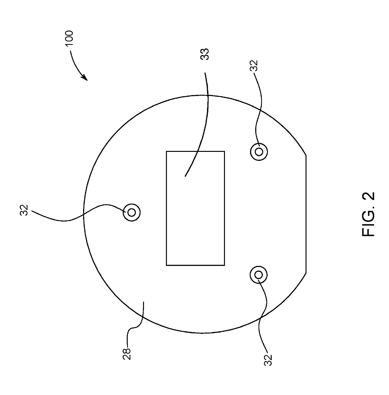
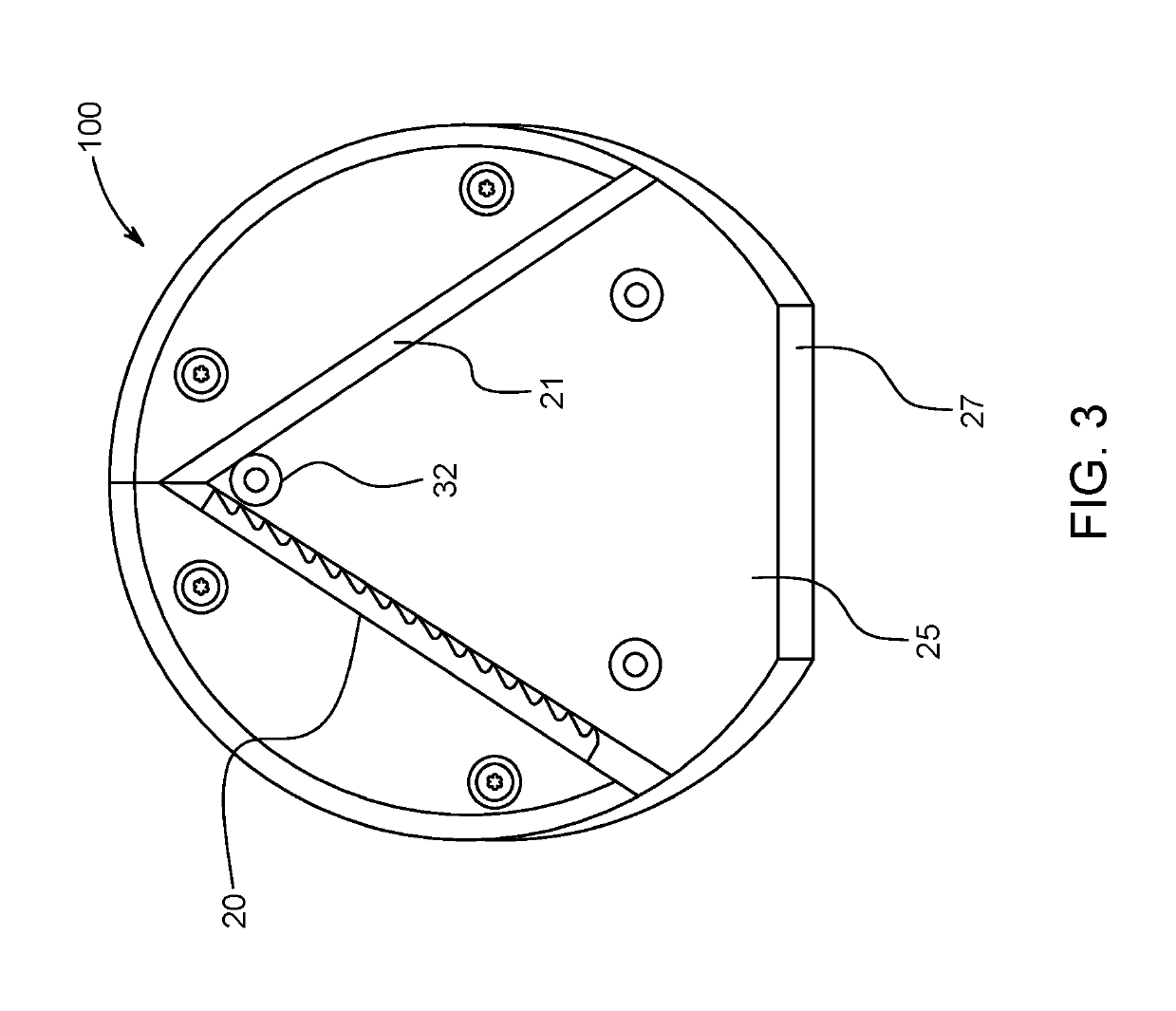
[0009]The present invention provides a jar opener that is mountable on the undersurface of a cabinet or other flat surface that includes an opening to receive a lid of a jar. This opening is a V-shaped which is mounted on a semicircular base. The V-shape opening is created by using a first lid brace and a second lid brace that are attached to the base of the opener. A receiving opening is created to receive the lid and brace the lid against a blade. The blade is provided on the first lid brace and therefore secures the lid into a stationary position while an individual may turn the jar preferably using two hands to loosen the lid on the jar. The present invention includes openings in the base to mount the base onto the surface and screws are used to mount the respective braces in place onto the base of the jar lid opener.
[0010]A jar lid opener 100 according to present invention is depicted in FIGS. 1-5, where FIG. 1 shows a top view of the jar lid opener 100. In this top view, a first lid brace 22 is shown and a second lid brace 24 is shown abutting the first lid brace 22 both of which are mounted on a base below each brace. Mounting Screws 30 are shown that are used to secure the braces 22, 24 to a base. The braces 22, 24 form an opening 25 that receives a jar lid. The lid brace 22 includes a pair of serrated blades 20. These serrated blades 20 are preferably made from hardened steel. The serrated blades 20 provide a means to brace a lid of a jar after being placed into the opening 25. The brace 24 includes an abutting edge 21 to support the jar lid into place while opening. Holes 32 are provided within the base to receive screws that allow the base to be mounted on the underside of a kitchen cabinet. Once in place a user places the lid within the opening 25, braces the lid against blades 20 and turns the jar to release the lid. The angle between lid brace 22 and lid brace 24 is preferably 70 degrees which provides an optimum angle to allow the lid to open with less force as opposed to the prior art.
[0011]FIG. 2 is a rear view of the lid opener 100, where holes 32 are shown for mounting, where double stick tape 33 is attached to the base to aid in mounting the jar opener to the underside of a cabinet. A perspective view the pair of serrated blades 20 are clearly shown in FIGS. 3 and 5 with the opening 25 provided between the two lid braces 22, 24. A flat edge 27 is also shown in FIG. 3 with the remaining edge being substantially circular. FIG. 4 shows a side view direct toward the blades 20 and abutting edge 21. The foregoing descriptions of specific embodiments of the present invention have been presented for purposes of illustration and description. They are not intended to be exhaustive or to limit the invention to the precise forms disclosed, and obviously many modifications and variations are possible in light of the above teaching. The exemplary embodiment was chosen and described in order to best explain the principles of the invention and its practical application, to thereby enable others skilled in the art to best utilize the invention and various embodiments with various modifications as are suited to the particular use contemplated.

PUM

no PUM

Description & Claims & Application Information

We can also present the details of the Description, Claims and Application information to help users get a comprehensive understanding of the technical details of the patent, such as background art, summary of invention, brief description of drawings, description of embodiments, and other original content. On the other hand, users can also determine the specific scope of protection of the technology through the list of claims; as well as understand the changes in the life cycle of the technology with the presentation of the patent timeline. Login to view more.
Why Eureka
Try Eureka