Capless closure device for a fuel tank filler neck of a vehicle and a vehicle including such a device

a technology of capless closure and filler neck, which is applied in the direction of vehicle components, transportation and packaging, propulsion parts, etc., can solve the problems of adding complexity and parts to the design of the filler neck, and achieve the effect of simplifying the drainage of the capless closure devi

Active Publication Date: 2019-10-03
VOLVO CAR CORP
View PDF2 Cites 1 Cited by
  • Summary
  • Abstract
  • Description
  • Claims
  • Application Information

AI Technical Summary

Benefits of technology

[0011]By this first embodiment of a capless closure device, a capless closure device comprising an integrated drain passage is provided. The drain passage is closed off during refuelling of the vehicle in a passive way by the rubber sleeve of a fuel nozzle, such that no additional closing covers or the like are required. In this way, a simplified drainage of a capless closure device is obtained. The invention is made possible by separating the latch edge for the fuel nozzle from the sealing edge for the sealing of the flap door. By this separation in a vertical direction, wear of the latch edge will not influence the sealing of the flap door since the sealing edge will be positioned below the latch edge. The flap door will thus be sealed in a tight manner throughout the life of the vehicle, regardless of the wear of the latch edge.
[0012]According to one example embodiment, the outlet drain opening exits in the bearing surface of the capless closure device, which is the surface surrounding the circular filler opening of the fuel tank filler neck. When a fuel nozzle is inserted into the filler opening, the rubber sleeve of the fuel nozzle will bear on the bearing surface and the width of the edge of the rubber sleeve will cover the outlet drain opening of the drain passage. In this way, no fuel vapour emissions may escape the fuel tank filler neck during refuelling.

Problems solved by technology

One disadvantage of such a solution is that the latching edge for the filler nozzle is the same as the sealing edge for the sealing of the closure flap of the capless closure.
When the latching edge wears due to wear from the filling nozzle, the sealing edge will degrade and may cause leakage, such that contaminants may enter the inlet opening to the gas tank or that fuel vapour emissions may escape the vehicle fuel system.
Such a solution adds complexity and parts to the design of the filler neck.

Method used


Image

  • Capless closure device for a fuel tank filler neck of a vehicle and a vehicle including such a device
  • Capless closure device for a fuel tank filler neck of a vehicle and a vehicle including such a device

Examples


Embodiment Construction

[0019]The embodiments of the invention with further developments described in the following are to be regarded only as examples and are in no way to limit the scope of the protection provided by the patent claims.

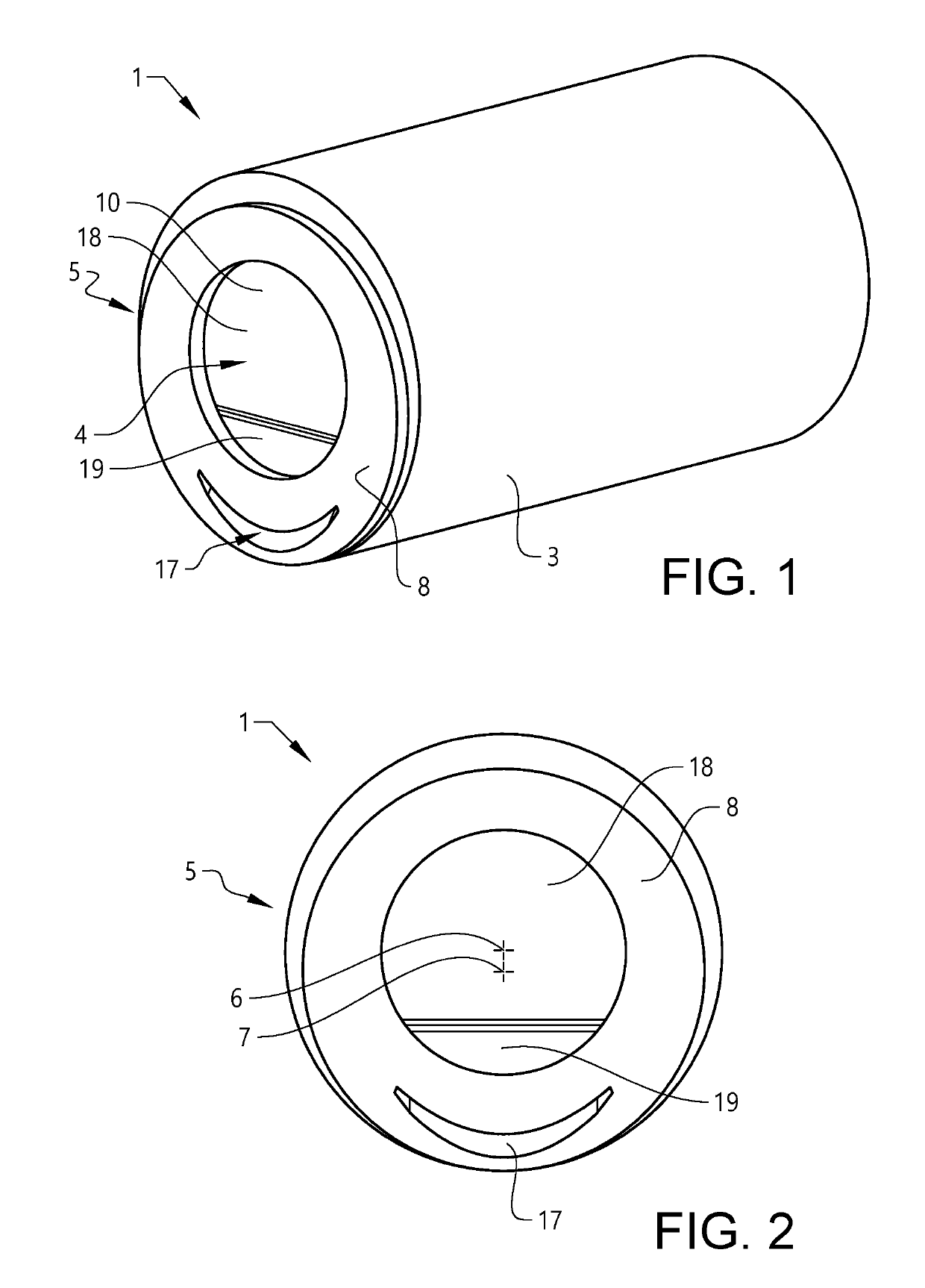
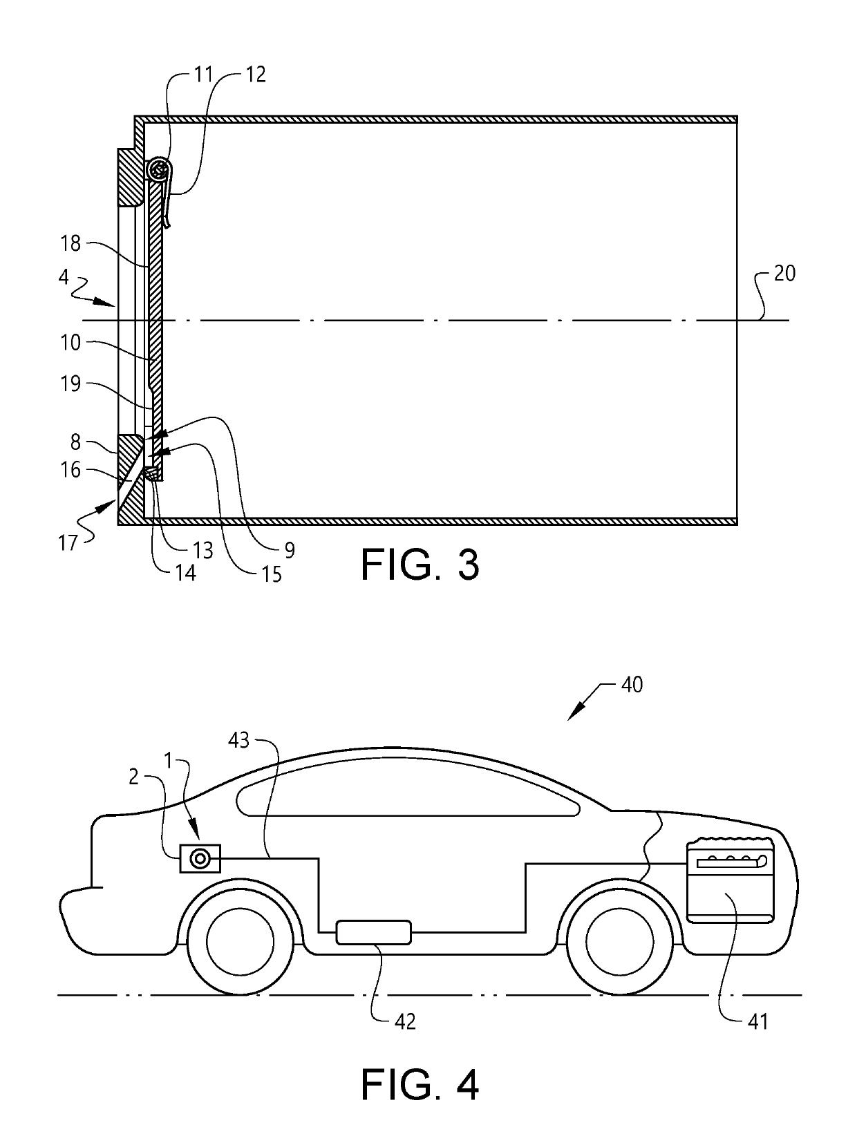
[0020]FIGS. 1 to 3 show a first embodiment of a capless closure device, and FIG. 4 shows a vehicle comprising such a capless closure device.

[0021]The capless closure device 1 comprises in the shown example a tube shaped housing 3 to be comprised in a fuel tank filler neck 2 of the fuel system of a vehicle. The body 3 comprises in one end an end plate 5 provided with a circular opening 4 adapted to receive a fuel nozzle. The end plate 5 is circular and provided with a bearing surface 8. The circular opening 4 is in the shown example positioned asymmetrically in the bearing surface 8, with the centre 6 of the circular opening 4 displaced from the centre 7 of the bearing surface 8. Depending on the size of the end plate, the bearing surface may also be positioned in a symmetri...


PUM


Abstract

A capless closure device including a body, an end plate provided with a circular opening adapted for receiving a fuel nozzle, and a flap door adapted to close the circular opening, where the capless closure device includes a latch edge arranged at the lower edge of the circular opening and a spaced apart sealing edge, and where an inlet drain opening is arranged between the latch edge and the sealing edge. The advantage of the invention is that a capless closure device with an integrated drain passage is provided in a cost-effective way.

Description

CROSS-REFERENCE TO RELATED APPLICATION[0001]The present patent application / patent claims the benefit of priority of co-pending European Patent Application No. 18165048.2, filed on Mar. 29, 2018, and entitled “CAPLESS CLOSURE DEVICE FOR A FUEL TANK FILLER NECK OF VEHICLE AND A VEHICLE COMPRISING SUCH A DEVICE,” the contents of which are incorporated in full by reference herein.TECHNICAL FIELD[0002]The present invention relates to a capless closure device for closing a refueling port of a vehicle, where the closure device comprises an integrated water drainage.BACKGROUND ART[0003]Vehicles comprising an internal combustion engine are subjected to a plurality of different legislative requirements and regulations. One of these requirements and regulations is directed to fuel vapour emissions while refuelling a vehicle. Different countries or markets may have different requirements. In some countries, the size of the fuel inlet is specified such that it corresponds to the filler nozzle in...

Claims


Application Information

Patent Timeline
Patent Type & Authority Applications(United States)
IPC IPC(8): B60K15/04
CPCB60K2015/0419B60K2015/0451B60K15/04B60K2015/0461B60K2015/048B60K15/0406B60K2015/0429
Inventor ÅHLBERG, JOHAN
Owner VOLVO CAR CORP
Why Eureka
Try Eureka