Anti-slip attachment and drainage system for prosthetics

a technology of anti-slip and protruding system, applied in the field of prosthetics, can solve the problems of extraneous pivoting, rotation and shift during ambulation, add to discomfort, and not a convenient solution, and achieve the effects of avoiding fluid build-up, preventing lateral, pivotal and proximal shift, and simple fluid drainag

Active Publication Date: 2010-08-10
KISS TECH LLC
View PDF4 Cites 55 Cited by
  • Summary
  • Abstract
  • Description
  • Claims
  • Application Information

AI Technical Summary

Benefits of technology

[0014]It is another object to combine a dual-lanyard (KISS® type) attachment system with a locking suction liner and (Harmony® type pump) to provide a dual-lanyard vacuum-assisted suction, plus top-side and lower mechanical lanyard-type attachments to prevent all extraneous up and down motion, pivoting, rotation and shift.
[0015]It is another object to combine the benefits of the existing suspension-type Harmony System with vacuum-assisted suction locking liner and moisture evacuation, with a dual-lanyard mechanical fastening strap running upward along the side of the socket to prevent extraneous up and down motion, pivoting, rotation and shift during ambulation.
[0016]It is still another object to provide a prosthetic anchoring system as described above that remains easy to put on, and to readjust / tighten the fit of the liner in the socket from a sitting position.
[0021]In accordance with one embodiment of the invention, the vacuum tube may be fastened to the artificial limb and equipped with a distal one-way valve for simple drainage of fluid from the liner.
[0022]Alternatively, a vacuum pump such as shown and described in the '253 patent to Caspers may be attached to the connector block, and the vacuum tube attached to the vacuum pump to introduce vacuum suction into the liner thereby evacuate air as well as fluid (sweat) out of the liner, thereby sealing the liner to the patient's residual limb and avoiding fluid build-up. This way, the liner is securely anchored to the residual limb in the socket by total contact induced by the vacuum force of the pump, and further secured by the dual-lanyard formed by the first strap and buckle inserted through the socket and fastened to the second strap which form a suspension fit that prevents lateral, pivotal and proximal shift. The vacuum pump may also serve as a shock absorber for the artificial limb.

Problems solved by technology

There are a number of difficult goals for the design of transfemoral and / or transtibial prostheses (above & below the knee).
Stability is a common problem as many existing anchoring systems use a single attachment point to hold the residual limb in place, and this typically leads to extraneous pivoting, rotation and shift during ambulation.
This is not a convenient solution.
However, this tends to squeeze the limb unevenly and adds to discomfort.
Moreover, the radial pressure tends to pop the limb out of the socket over the course of a day.
However, it has been found that many amputees lack the room for, are unable to tolerate, or have difficulty engaging the distal pin.
Others complain of pain associated with engagement of the pin.
Again, many amputees lack the room for, are unable to tolerate, or have difficulty engaging a distal pin.
Unfortunately, this is difficult with the suspension Harmony System because the suction liner is suspended over an evacuation nozzle at the bottom of the socket that evacuates moisture (sweat) outside of the socket.
Despite the advantages, the '682 patent could not heretofore be used with a locking suction liner (liner pin mating with socket) as with the Harmony System, and the '682 patent provides no drainage solution in and of itself.
Integrating a drainage system into a prosthetic attachment is no easy matter without compromising comfort or stability.
Just the slightest discontinuity or protruberance inside the liner can be unbearable to a patient over time.

Method used


Image

  • Anti-slip attachment and drainage system for prosthetics
  • Anti-slip attachment and drainage system for prosthetics
  • Anti-slip attachment and drainage system for prosthetics

Examples


Embodiment Construction

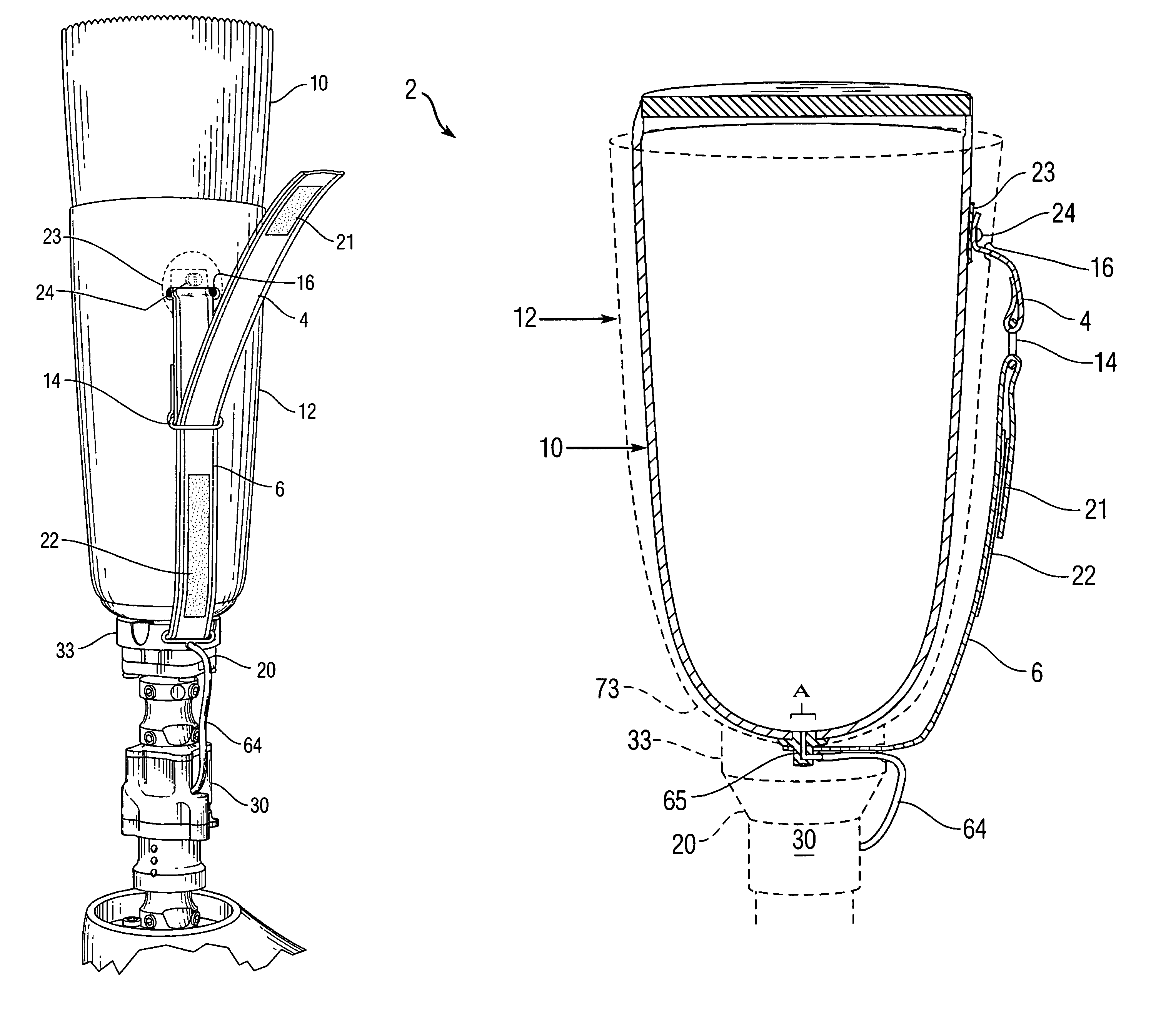
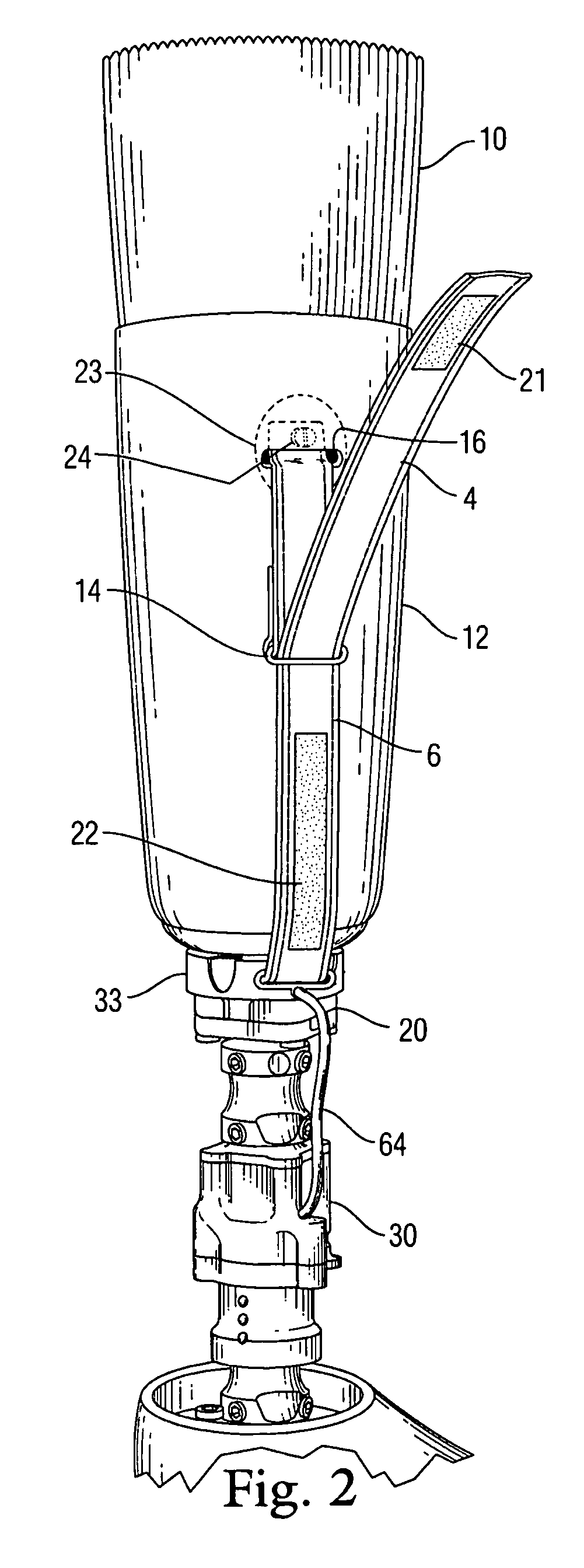
[0032]The present invention is a prosthetic attachment system for transfemoral (above-knee) or transtibial (below knee) amputees that incorporates a moisture evacuation feature into a dual-lanyard attachment system, and optionally adds a vacuum-assisted locking suction liner to provide unmatched comfort and stability against extraneous up and down motion, pivoting, rotation and shift during ambulation.

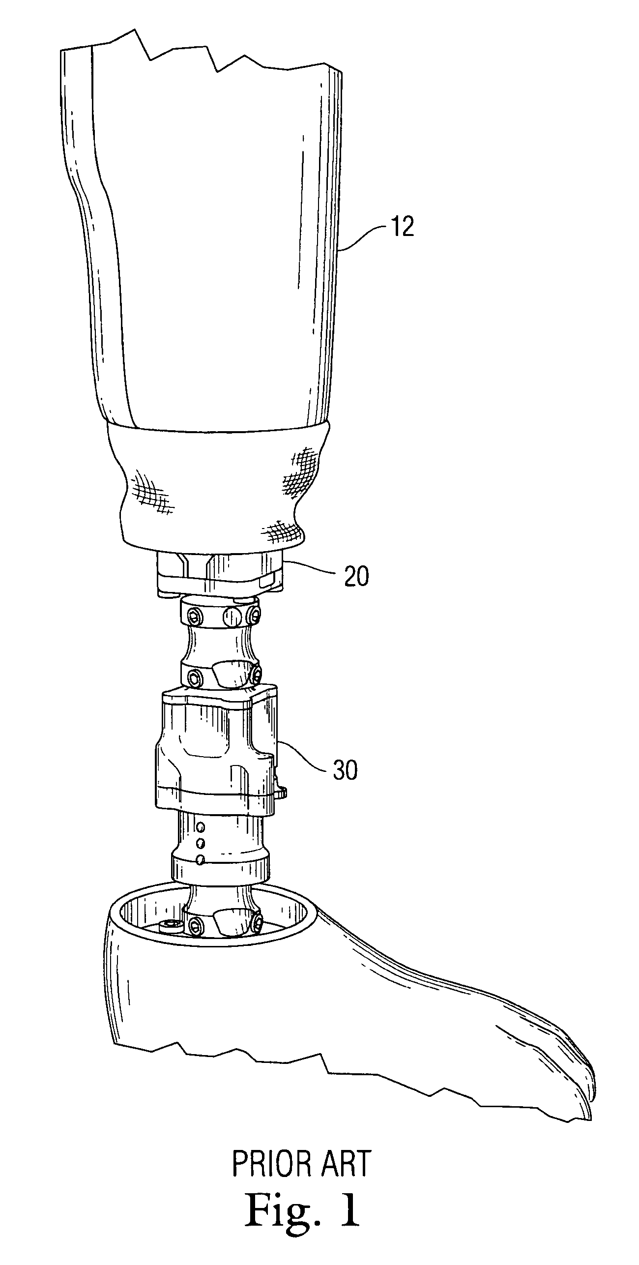
[0033]FIG. 2 is a perspective view of the prosthetic attachment system according to a first embodiment of the present invention, which integrates a moisture evacuation feature into a dual-lanyard attachment system, and also adds a vacuum-assisted locking suction liner. Toward this latter goal the attachment system incorporates some conventional elements of the above-described Harmony System such as a hard socket 12, nonporous gel liner 10 fitted over the residual limb and inserted in the socket 12, and a vacuum pump 30 attached via a connector block 20 beneath the socket 12 for drawing...


PUM


Abstract

An anchoring system for a transtibial or transfemoral (above or below the knee) prosthesis. A gel liner is inserted into a socket, and the liner has a dual-strap attachment system including an upper strap and buckle attached upwardly to the liner and passing out through the socket, and a lower strap attached distally to the liner. The liner also has a port attached at a lower distal end for introducing a vacuum into the liner and for evacuating fluids (sweat) therefrom. To accomplish the foregoing, an annular centering puck is attached at the distal end of the socket (at the aperture), the puck having a generally concave side in communication with the aperture for seating the liner therein. The centering puck is formed with a dual passage there through that passes both a vacuum tube and lower strap outward from the liner to exterior of the socket. A vacuum pump is coupled to the vacuum tube, and the liner is securely anchored in the socket by total contact induced by the vacuum force of the pump, and further secured by the first strap and buckle inserted through the socket and fastened to the second strap (passing out through the puck and inserted through the buckle, tightened, and closed upon itself to form a suspension fit which prevents lateral, pivotal and proximal shift.

Description

CROSS-REFERENCE TO RELATED APPLICATION(S)[0001]The present application derives priority from U.S. Provisional Patent Application No. 60 / 704,237 filed: Aug. 1, 2005.BACKGROUND OF THE INVENTION[0002]1. Field of the Invention[0003]The present invention relates to prostheses and, more particularly, to an anti-slip anchoring system with drainage feature that securely anchors a suction liner with a top-side and lower lanyard-type attachment to prevent extraneous motion for above-the-knee and below-the-knee amputation patients, and which drains moisture from sweat to improve comfort without sacrificing stability.[0004]2. Description of the Background[0005]There are a variety of different types of prosthetic devices for patients that have had either transfemoral (above-knee) or transtibial (below the knee) amputation. Typically, post-operative prosthetic devices for either type of amputation patients begin with a liner, which is rolled on to the residual limb. The liner is a soft, stretchy ...

Claims


Application Information

Patent Timeline
Patent Type & Authority Patents(United States)
IPC IPC(8): A61F2/80
CPCA61F2/60A61F2/78A61F2002/30464A61F2002/30507A61F2002/742A61F2002/7868A61F2002/7881A61F2002/802A61F2220/0025A61F2220/0075A61F2002/30462A61F2002/7831A61F2/742
Inventor MANTELMACHER, H. LEE
Owner KISS TECH LLC
Why Eureka
Try Eureka