Tool turret rotating structure and tool turret rotating method

A technology of rotating structure and turret, applied in the direction of tool holder, etc., can solve the problems of low rotation accuracy, loose tool handle, high cost, etc., to prevent the turret from swinging, prevent the turret from moving up and down, and achieve good stability. Effect

Inactive Publication Date: 2013-02-13
HANGZHOU BAKER MASCH CO LTD
View PDF0 Cites 0 Cited by
  • Summary
  • Abstract
  • Description
  • Claims
  • Application Information

AI Technical Summary

Problems solved by technology

[0002] In the current background technology, the locking method of the turret handle adopts the rear pull locking method. There is a pull nail at the end of the handle. The oil pressure controls the knife cylinder, and the knife cylinder acts on the butterfly spring to make the mechanical three-claw When working, the mechanical claw grabs the pull nail and pulls it tightly to the tool handle; the general turret needs to be equipped with a VDI tool holder (Fig. 2-1), and it is a special part that cannot be interchanged in turning, milling, boring, drilling and tapping. , not only the VDI tool seat is expensive, the tool handle is not easy to replace, but also the tool handle is prone to loosening during processing. In addition, when machining porous parts on the same surface, it needs to be processed step by step. Drilling and tapping cannot be done at one time. When the workpiece is different, it is not possible to install a multi-axis device, so it is a waste of man-hours and the processing efficiency is not good; in addition, in the main shaft transmission mode, the general main shaft transmission adopts spline transmission, and the spline manufacturing process is cumbersome and expensive
The position of the turret is easy to yaw, and the turret moves up and down (because the turret only performs radial rotation), which cannot effectively reduce friction; in addition, the rotating structure of the turret adopts a two-plate clutch structure. When the turret needs to rotate, The turret can only rotate when the indexing tooth plate is separated from the rising base, so the rotation accuracy is low and the stability is not good

Method used


Image

  • Tool turret rotating structure and tool turret rotating method

Examples


Embodiment 1

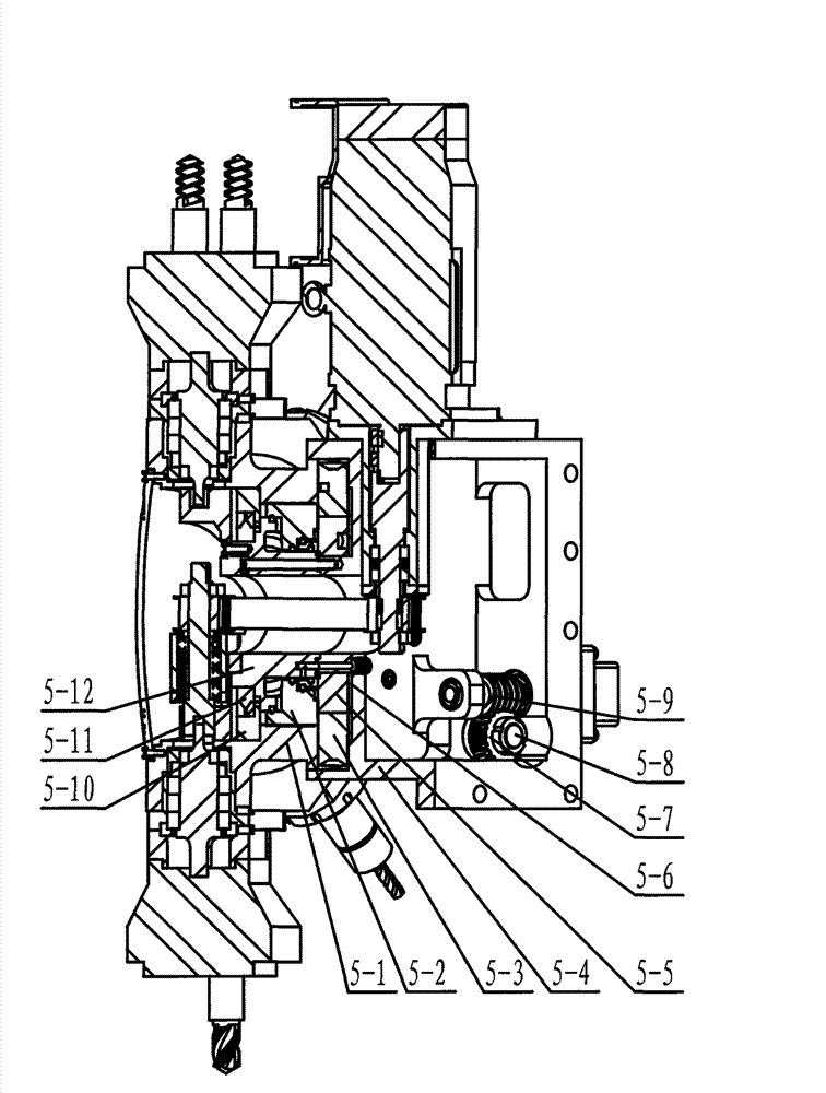
[0011] Embodiment 1: see attached figure 1 . A turret rotation structure, which includes a turret 5-1, the rotation of the turret 5-1 adopts a three-plate clutch structure and consists of an indexing toothed plate A5-3, an indexing toothed plate B5-2, an indexing tooth Disk C5-5 and friction plate 5-6 are composed of indexing toothed plate A5-3 fastened on turret 5-1, indexing toothed plate C5-5 is fastened on base 5-4, and indexing toothed plate B5 -2 can be used for piston movement, the teeth of the indexing toothed plate A5-3 and the indexing toothed plate C5-5 are aligned, and the indexing toothed plate B5-2 is opposite to the indexing toothed plate A5-3 and the indexing toothed plate C5- 5. Engage and lock the teeth. The servo motor and the worm 5-9 drive the worm gear 5-7 to rotate through the worm. The worm gear is installed on the cylindrical helical gear shaft 5-8. Mesh with cylindrical helical gear shaft 5-8 to drive turret 5-1 to rotate together; friction plate 5-...

Embodiment 2

[0012] Embodiment 2: On the basis of Embodiment 1, the rotation method of the turret rotation structure, the indexing toothed plate A is fastened on the turret, the indexing toothed plate C is fastened on the base, and the indexing toothed plate B can be used as Piston movement, indexing toothed disc A and indexing toothed disc C are aligned and placed, indexing toothed disc B engages and locks the indexing toothed disc A and indexing toothed disc C, when the turret needs to rotate , using oil pressure to disengage the indexing tooth plate B, the servo motor is connected to the worm, and the worm is controlled to rotate at the same speed to drive the worm wheel. The worm wheel is installed on the cylindrical helical gear shaft, and the outer circular helical teeth of the indexing tooth plate A The meshing of cylindrical helical gear shaft and gear drives the turret to rotate together to realize the function of turret rotation; during the rotation process, the turret can rotate ...


PUM


Abstract

The invention relates to a turret type tool turret rotating structure and a tool turret rotating method for a lathing and milling combined tool turret of a CNC lathe and a machining center. The structure comprises a tool turret; the tool turret adopts a three-plate clutch structure for rotation, and consists of a dividing gear plate A, a dividing gear plate B, a dividing gear plate C and a friction plate, wherein the dividing gear plate A is tightly fixed on the tool turret; the dividing gear plate C is tightly fixed on a base; the dividing gear plate B can perform piston movement; tooth sheets of the dividing gear plate A and the dividing gear plate C are arranged in alignment; the dividing gear plate B is meshed and locked with the tooth sheets of the dividing gear plate A and the dividing gear plate C; a servo motor and a worm drive a worm wheel to rotate through the worm; the worm wheel is arranged on a cylindrical helical gear axis; and cylindrical helical teeth of dividing gear plate A are meshed with a gear on the cylindrical helical gear shaft to drive the tool turret to rotate together.

Description

technical field [0001] The invention relates to a turret rotating structure and method for turning, milling, and compound turrets of numerically controlled lathes and machining centers, and belongs to the field of turret rotating structure manufacturing. Background technique [0002] In the current background technology, the locking method of the knife handle of the turret adopts the rear-pull locking method. There is a pull nail at the end of the knife handle, and the oil pressure controls the knife cylinder. When working, the mechanical claw grabs the pull nail and pulls it tightly to the tool handle; the general turret needs to be equipped with a VDI tool holder (Fig. 2-1), and it is a special part that cannot be interchanged in turning, milling, boring, drilling and tapping. , not only the VDI tool seat is expensive, the tool handle is not easy to replace, but also the tool handle is prone to loosening during processing. In addition, when the same surface needs to be pro...

Claims


Application Information

Patent Timeline
Patent Type & Authority Patents(China)
IPC IPC(8): B23B29/32
Inventor 廖竹霖
Owner HANGZHOU BAKER MASCH CO LTD
Why Eureka
Try Eureka