Damping force control device

a control device and force technology, applied in the direction of braking system, control system, braking components, etc., can solve the problems of insufficient damped/attenuated damp/weakening impact, and inability to attenuate/reduce the vibration of the vehicle body

Active Publication Date: 2019-11-21
TOYOTA JIDOSHA KK
View PDF0 Cites 6 Cited by
  • Summary
  • Abstract
  • Description
  • Claims
  • Application Information

AI Technical Summary

Benefits of technology

[0018]Hereby, in the case where the specific condition is satisfied, the shock absorber corresponding to

Problems solved by technology

Therefore, when at least one of the wheels becomes the ungrounded wheel, it is likely that “the damping force generated by the shock absorber corresponding to each of “grounded wheels which touch the ground” cannot attenuate/reduce the vibration of the vehicle body (the sprung mass part) sufficiently.
This degrades/worsens “a ride comfortability and a drivabi

Method used


Image

  • Damping force control device
  • Damping force control device
  • Damping force control device

Examples


first embodiment

(Configuration)

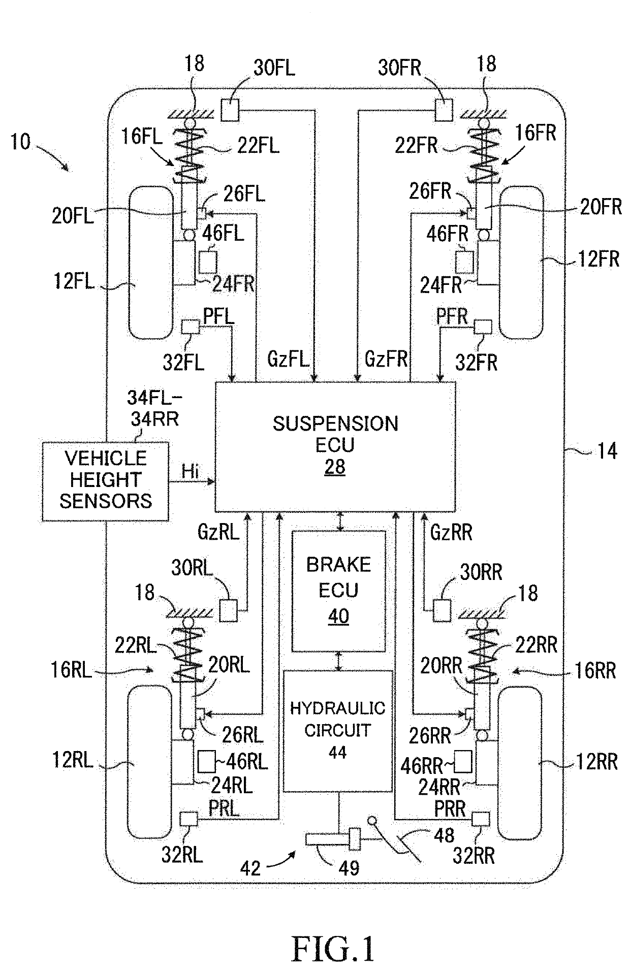
[0035]As shown in FIG. 1, a damping force control device 10 (hereinafter, referred to as a “first device”) according to a first embodiment is applied to a vehicle 14 comprising a front left wheel 12FL, a front right wheel 12FR, a rear left wheel 12RL, and a rear right wheel 12RR. Each of the front left wheel 12FL and the front right wheel 12FR is a steered wheel, and each of the rear left wheel 12RL and the rear right wheel 12RR is a non-steered wheel. The front left wheel 12FL and the front right wheel 12FR are suspended from a vehicle body 18 by suspensions 16FL and 16FR, respectively. The rear left wheel 12RL and the rear right wheel 12RR are suspended from the vehicle body 18 by suspensions 16RL and 16RR, respectively. Hereinafter, when the front left wheel 12FL, the front right wheel 12FR, the rear left wheel 12RL, and the rear right wheel 12RR do not need to be distinguished from each other, they are referred to as “wheels 12”. When the suspension 16FR through 1...

second embodiment

[0080]The damping force control device (hereinafter, referred to as a “second device”) according to a second embodiment will next be described. The second device differs from the first device in that the second device determines whether each of the wheels 12FL through 12RR is the ungrounded wheel or the grounded wheel, based on (using) the corresponding one of the rotation speeds Vi. Hereinafter, the above difference point will be described mainly.

[0081]The CPU of the suspension ECU 28 of the second device is configured to execute a routine represented by a flowchart shown in FIG. 5, in place of the routine represented by the flowchart shown in FIG. 3, every time a predetermined time period elapses. In FIG. 5, the same Steps as the Steps shown in FIG. 3 are denoted with common step symbols for the Steps shown in FIG. 3, and description thereof is omitted.

[0082]When a predetermined timing has come, the CPU starts processes from Step 500. When the vehicle speed Vs is equal to or lower...

modification example of second embodiment

[0094]The CPU according to this modification example calculates an estimation rotation speed Vb instead of the average rotation speed Va at Step 510. In more detail, an unillustrated shift position sensor transmits a signal indicative of a position of an unillustrated shift lever operated by the driver to the suspension ECU 28. An unillustrated drive ECU transmits a signal indicative of a gear position realized / set by an unillustrated transmission of the vehicle 14 to the suspension ECU 28. Furthermore, an engine rotation sensor transmits a signal indicative of a rotation speed of an engine which is a driving source of the vehicle 14 to the suspension ECU 28.

[0095]At Step 510, the CPU calculates the estimation rotation speed Vb of the wheels 12 based on “a gear ratio identified by the gear position” and the engine rotation speed. Furthermore, at Step 510, the CPU acquires the subtraction value Di by subtracting the estimation rotation speed Vb from the rotation speed Vi of each of t...


PUM


Abstract

A damping force control device 10 comprises vary damping shock absorbers, a detector, and a controller. Each of the shock absorbers sets damping coefficient from a minimum value to a maximum value in order to adjust damping force. The detector detects vertical vibration state quantity relating to vibration of the sprung mass. The controller performs an ordinary control for setting the damping coefficient based on the vertical vibration state quantity and according to a predetermined control law suitable for an assumption that all of the wheels touch ground. The controller performs, when at least one of the wheels is an ungrounded wheel which does not touch the ground and each of the other wheels is a grounded wheel which touches the ground, a specific control for setting the damping coefficient of the shock absorber corresponding to the grounded wheel to a first specific value greater than the minimum value.

Description

BACKGROUNDTechnical Field[0001]The present disclosure relates to a damping force control device for setting a damping coefficient of a shock absorber arranged between a sprung mass part and an unsprung mass part of each of wheels.Related Art[0002]Hitherto, there has been known a damping force control device with a variable damping shock absorber. Such a shock absorber is configured to vary a damping coefficient.[0003]As proposed in Japanese Patent Application Laid-open No. 2017-206161, such a damping force control device (hereinafter, referred to as a “conventional device”) calculates a target damping coefficient which is appropriate to damp / attenuate vibration of a sprung mass part (namely, a vehicle body) based on a predetermined control law and a vertical state quantity of the sprung mass part. The conventional device controls the shock absorber in such a manner that the damping coefficient coincides with (becomes equal to) the target damping coefficient.SUMMARY[0004]While the ve...

Claims


Application Information

Patent Timeline
IPC IPC(8): B60G17/0195B60G17/0165B60T8/175B60G17/015B60T8/26
CPCB60G17/0195B60T2260/06B60G2400/252B60T2250/00B60T8/175B60G17/0165B60T2210/14B60T8/26B60G2204/62B60G2200/10B60G2400/208B60G17/0152B60G2204/8102B60G2500/104B60G2400/821B60G2204/80B60G2800/162B60T2270/20B60G2600/182B60G17/015B60G17/019B60G17/01933B60G17/06B60G17/018B60G17/08
Inventor OKIMURA, KOHTAROHTABADA, MASAAKITAKAMURA, YOSHINORIMASUTANI, RYO
Owner TOYOTA JIDOSHA KK
Why Eureka
Try Eureka