Fins with improved fluid dynamic properties

a technology of fluid dynamic properties and fins, which is applied in the direction of waterborne vessels, special-purpose vessels, vehicles, etc., can solve the problems of increasing increasing the pressure, and increasing the drag, etc., and achieves the effect of improving the fluid dynamic properties, reducing the surface area of the foil, and reducing the risk of rusting or significant corrosion

Active Publication Date: 2020-01-09
FLYING FIN SYST
View PDF3 Cites 3 Cited by
  • Summary
  • Abstract
  • Description
  • Claims
  • Application Information

AI Technical Summary

Benefits of technology

[0129]In one embodiment of the invention, a portion of, or the entire fin is constructed from, or comprises, a metal or a metal alloy. The metal is preferably strong, light weight, and incapable of rusting or significant corrosion.
[0130]In a preferred embodiment, the metal is titanium. Preferably, the metal is a titanium alloy. More preferably, the titanium alloy comprises between approximately 3.5% to 4.5% vanadium, and between approximately 5.5% to 6.75% aluminium. Evan more preferably, the titanium alloy comprises approximately 4% vanadium and approximately 6% aluminium. This titanium alloy can

Problems solved by technology

As a result, more water will flow past the flat surface of the foil creating an area of high pressure.
The problem is at higher speeds that additional drag will develop turbulence and stall the flow across the foil.
However, more surface area causes greater drag and slows a board d

Method used


Image

  • Fins with improved fluid dynamic properties
  • Fins with improved fluid dynamic properties
  • Fins with improved fluid dynamic properties

Examples


Embodiment Construction

[0175]Those skilled in the art will appreciate that the invention described herein is susceptible to variations and modifications other than those specifically described. It is to be understood that the invention includes all such variations and modifications. The invention also includes all of the steps, features, compositions and compounds referred to or indicated in the specification, individually or collectively and any and all combinations or any two or more of the steps or features.

[0176]The present invention is not to be limited in scope by the specific embodiments described herein, which are intended for the purpose of exemplification only. Functionally equivalent products, compositions and methods are clearly within the scope of the invention as described herein.

[0177]Throughout this specification, unless the context requires otherwise, the word “comprise”, or variations such as “comprises” or “comprising”, will be understood to imply the inclusion of a stated integer or gr...


PUM


Abstract

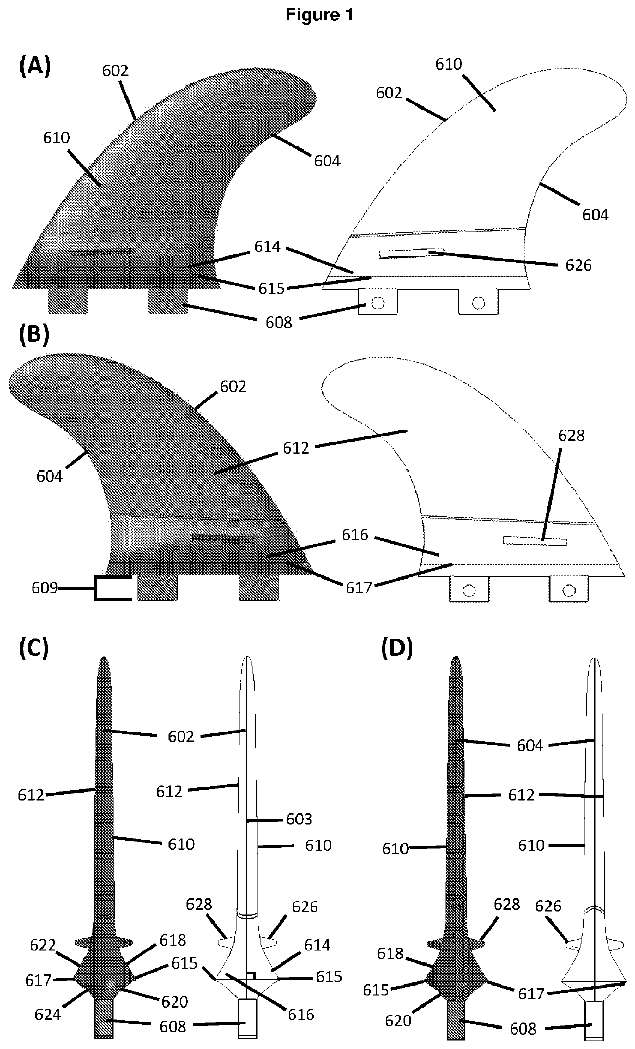
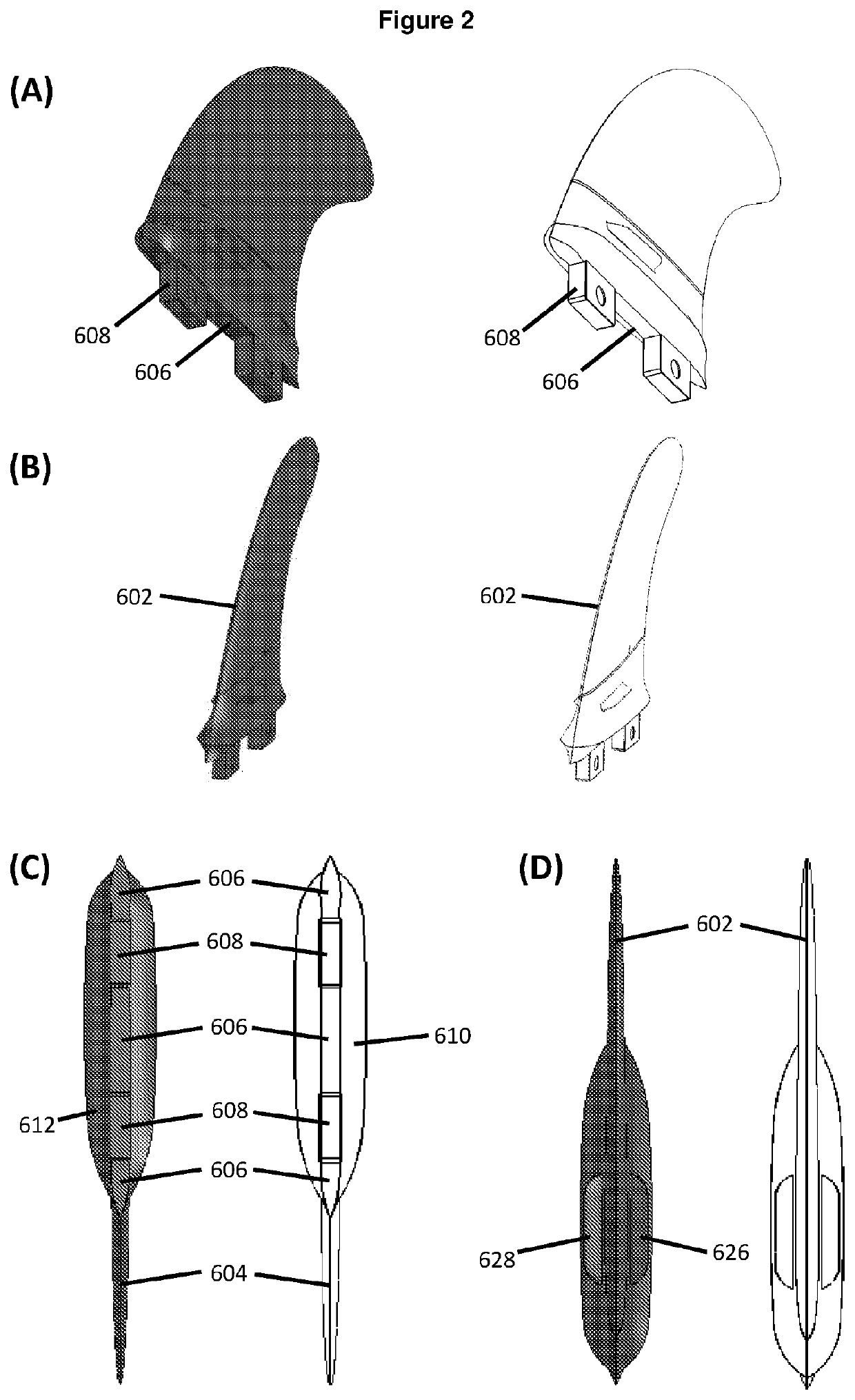
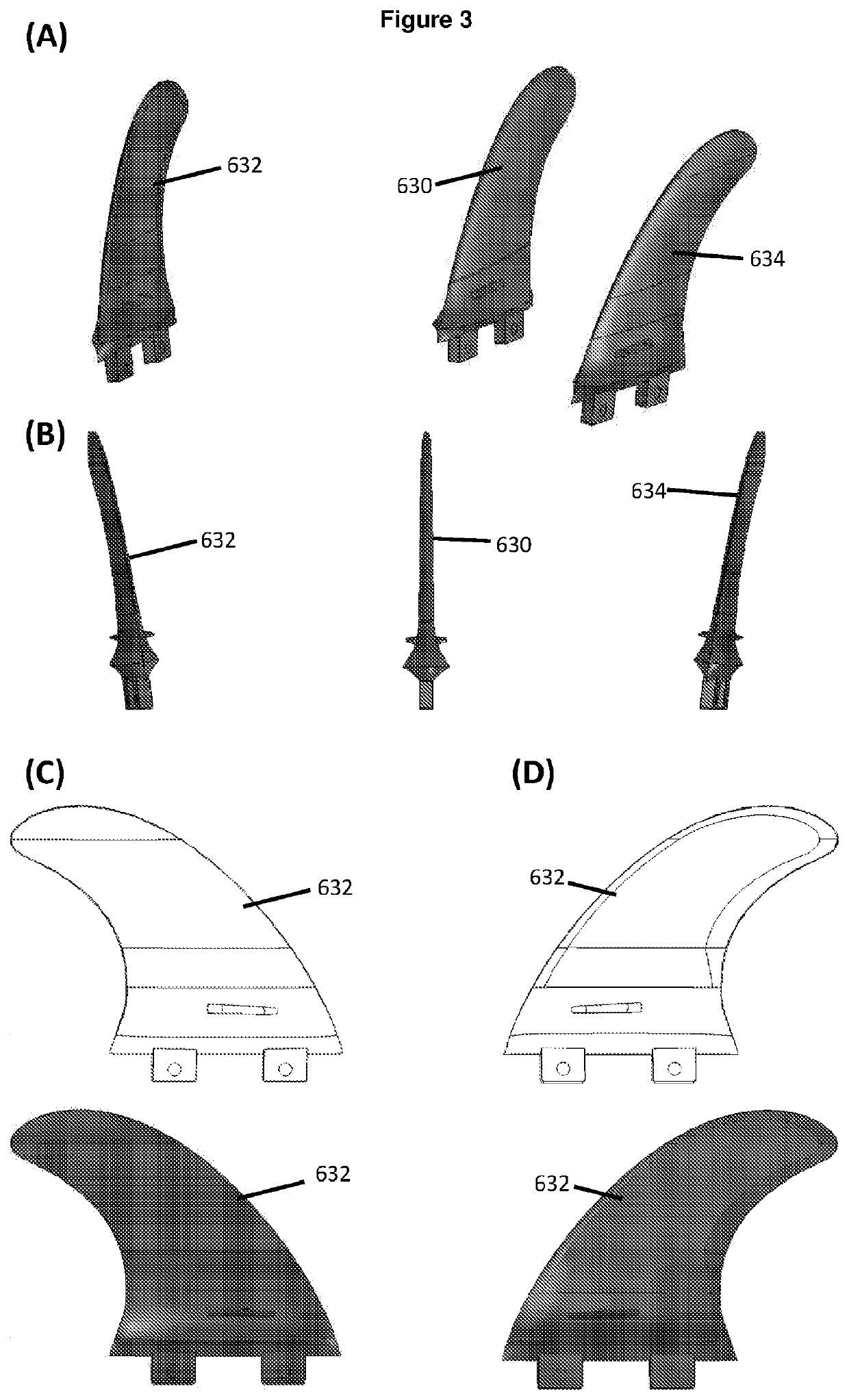
A fin for use on a surfboard, the fin comprising: a leading edge, a trailing edge, and a base, the base comprising at least one mount for mounting the fin onto a surfboard; a first and a second outer fin surface which meet along the leading edge and the trailing edge and abut the base; and a first ridge protruding laterally from the first outer fin surface, and/or a second ridge protruding laterally from the second outer fin surface; wherein the shape and configuration of the fin creates an area of lower water pressure around and in front of the fin, as well as disrupting and/or reducing the size of trailing vortices, resulting in additional forward thrust for the board on which the fin is mounted.

Description

TECHNICAL FIELD[0001]The present invention relates to the shape and configuration of a fin, keel, propeller, rudder, or plane on a vessel travelling on or under the water which can create an area of lower pressure around, and in front of it, as well as disrupt and / or reduce the size of trailing vortices resulting in additional forward thrust.BACKGROUND ART[0002]The following discussion of the background art is intended to facilitate an understanding of the present invention only. The discussion is not an acknowledgement or admission that any of the material referred to is or was part of the common general knowledge as at the priority date of the application.[0003]A surfboard, stand-up paddleboard (SUP), or similar type of board for use in water sports and other activities can be viewed in one sense as a summation of hydrodynamic surfaces. The surface of the bottom of the board in contact with water generates lift and affects speed. More importantly though, it is the fins working in ...

Claims


Application Information

Patent Timeline
IPC IPC(8): B63B35/79
CPCB63B35/793B63B2035/715B63B2035/009B63B32/66B63B34/26
Inventor MILLER, GLENNDIN GEORGE
Owner FLYING FIN SYST
Why Eureka
Try Eureka