Mechanical locking system for floor panels

a technology of locking system and floor panel, which is applied in the field of floor panel mechanical locking system, can solve the problems of low price of floor panel, and high cost of separate tongues and investments in special inserting equipment needed to insert flexible tongues into displacement grooves, and achieve the effect of increasing the locking strength

Active Publication Date: 2020-04-09
CERALOC INNOVATION AB
View PDF0 Cites 38 Cited by
  • Summary
  • Abstract
  • Description
  • Claims
  • Application Information

AI Technical Summary

Benefits of technology

The patent text describes a device that can securely lock two edges of a flexible part. The device uses a locking element that has two surfaces, one of which can be pressed inward, to lock the edges. The locked position is strong even when only a small amount of pressure is applied. The main technical effect of this device is the increased strength of the locking mechanism.

Problems solved by technology

The 5G system and similar system have been less successful in the low priced market segments.
The major reason is that the cost of the separate tongues and investments in special inserting equipment that is needed to insert a flexible tongue into a displacement groove are still regarded as rather high in relation to the rather low price of the floor panels.
All such attempts have failed especially when a floor panel comprises an HDF core.
The failure is based on major problems related to material properties and production methods.
One of the main reasons behind the failure is that bending of vertically protruding parts that are used for the vertical locking of edges is limited to about 50% of the floor thickness or to about 4 mm in an 8 mm thick laminate floor panel.
Other disadvantages compared to horizontal snapping are that HDF comprises a fibre orientation substantially parallel with the floor surface.
The main problem with one-piece systems based on flexible locking means extending along the joint is the fact that it is difficult to combine a high degree of flexibility in the horizontal direction, that is needed for an easy locking, with a low or preferably non-existent flexibility in the vertical direction that is needed for a high locking strength.
The main problem is that the tongue is flexible horizontally but also vertically and the vertical locking strength is very low.
The jumping tool forms deep cavities and this reduces the locking strength.
The essentially horizontal contact surfaces located on the locking element may increase the risk for squeaking sound when the panels are moving vertically since the outer part of the strip is not strong enough and is generally much more flexible than the inner part.
Locking with a flexible part that moves to its original position cannot create a strong locking and cannot eliminate production tolerances.
The forming of a slot in the thicker outer part of the strip is a difficult operation since an unnecessary high amount of material must be removed.
Only a few tongues may be formed at an edge and the locking strength is low especially in HDF material where the middle parts have a rather low density and flexibility.
Such locking systems are less suitable for thicker laminate panels since the large slit that is used to accommodate a locking protrusion results in low locking strength especially due to the fact that the flexibility in the vertical direction is generally larger than the flexibility in the horizontal direction.
The locking systems described above are also difficult to form in a cost efficient way with known production methods.

Method used


Image

  • Mechanical locking system for floor panels
  • Mechanical locking system for floor panels
  • Mechanical locking system for floor panels

Examples


embodiment 1

[0188]2. The set , wherein a cross section of the locking groove (14) or a cross section of the locking element (8) varies along the first and the second edge.

[0189]3. The set as in embodiment 1 or 2, wherein the slit wall (20a) is further configured to be bended at least partly back to an initial position of the slit wall (20a) during a final stage of the locking.

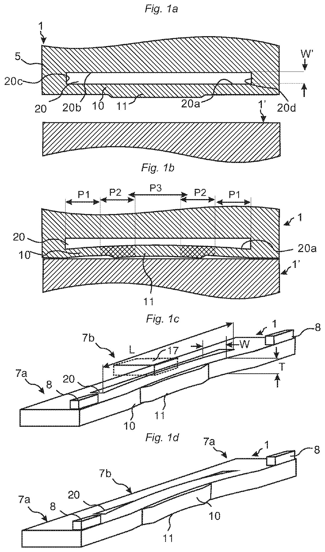
[0190]4. The set as in any one of the preceding embodiments 1-3, wherein the edge of the first panel (1) comprises upper (18) and lower (19) stabilizing surfaces that in the locked position overlap each other and prevent an upward bending of the slit wall (20a).

[0191]5. The set as in any of the preceding embodiments, wherein the first edge and the second edge are locked with vertical pretension between upper (16) and lower (15) support surfaces and between the upper (11a) and lower (11b) locking surfaces.

[0192]6. A set of essentially identical floor panels (1, 1′) provided with a mechanical locking system comprising a stri...

embodiment 6

[0200]7. The set , wherein the first edge comprises upper (18) and lower (19) stabilizing surfaces that in the locked position overlap each other and prevent an upward bending of one of the slit walls.

[0201]8. A set of essentially identical floor panels (1, 1′) provided with a mechanical locking system comprising a strip (6) extending horizontally from a lower part of a first edge and a downwardly open locking groove (14) formed in an adjacent second edge, wherein the strip (6) comprises an upwardly protruding locking element (8) comprising an upper locking surface (11a) at its upper and inner part and the locking groove (14) comprises a lower locking surface (11b) at its outer and lower part, the locking element (8) being configured to cooperate with the locking groove (14) and to lock the first and the second edge in a horizontal direction parallel to a main plane of a first and a second panel (1, 1′), the upper and lower locking surfaces (11a, 11b) being configured to lock the ad...

embodiment 8

[0207]9. The set , wherein the first edge comprises upper (18) and lower (19) stabilizing surfaces that in the locked position overlap each other and prevent an upward bending of a part of the locking element (8).

[0208]10. A set of essentially identical floor panels (1, 1′) provided with a mechanical locking system comprising a strip (6) extending horizontally from a lower part of a first edge and a downwardly open locking groove (14) formed in an adjacent second edge, wherein the strip (6) comprises an upwardly protruding locking element (8) and the second edge comprises a downwardly extending protrusion (36a) comprising a lower locking surface (11b) at its lower and outer part (32), the locking element (8) being configured to cooperate with the locking groove (14) and to lock the first and the second edge in a horizontal direction parallel to a main plane of a first and a second panel (1, 1′), wherein[0209]the first and the second edge in a locked position comprise a first edge se...


PUM


Abstract

Floor panels are shown, which are provided with a mechanical locking system that may be locked with a vertical displacement of a first panel against a second panel. The locking system includes a first rigid and a second flexible joint edge section with different locking functions. The first edge section provides a horizontal locking and the second section provides a vertical locking.

Description

CROSS REFERENCE TO RELATED APPLICATIONS[0001]The present application is a continuation of U.S. application Ser. No. 15 / 841,909, filed on Jul. 6, 2017, which is a U.S. national stage of International Application No. PCT / SE2016 / 050019, filed on Jan. 15, 2016, which claims the benefit of Swedish Application No. 1550033-3, filed on Jan. 16, 2015. The entire contents of each of U.S. application Ser. No. 15 / 841,909, International Application No. PCT / SE2016 / 050019, and Swedish Application No. 1550033-3 are hereby incorporated herein by reference in their entirety.TECHNICAL FIELD[0002]The disclosure generally relates to the field of mechanical locking systems for floor panels and building panels. The disclosure shows floorboards, furniture components, locking systems and production methods.FIELD OF APPLICATION OF THE INVENTION[0003]Embodiments of the present invention are particularly suitable for use in floating floors, which are formed of floor panels having of one or more upper layers co...

Claims


Application Information

Patent Timeline
Patent Type & Authority Applications(United States)
IPC IPC(8): E04F15/02E04F15/10
CPCE04F15/102E04F2201/041E04F15/02038E04F2201/021E04F2201/0146E04F2201/0123E04F2201/0138
Inventor PERVAN, DARKO
Owner CERALOC INNOVATION AB
Why Eureka
Try Eureka