Mechanical locking system for floor panels

a technology of locking system and floor panel, which is applied in the field of floor panel mechanical locking system, can solve the problems of low price of floor panel, and high cost of separate tongues and investments in special inserting equipment needed to insert flexible tongues into displacement grooves, and achieve the effect of increasing the locking strength

Active Publication Date: 2020-01-21
CERALOC INNOVATION AB
View PDF409 Cites 40 Cited by
  • Summary
  • Abstract
  • Description
  • Claims
  • Application Information

AI Technical Summary

Benefits of technology

[0036]A third specific objective is to prevent upward bending of flexible parts that are used to obtain a vertical locking of the edges.
[0058]According to one embodiment, the edges may be locked with vertical pretension between lower and upper support surfaces and between upper and lower locking surfaces. The locking element with its upper locking surface may only partly snap back to its original position, preferably less than about 80% of a first inward displacement, and may in a locked position be displaced upwardly in relation unlocked position due to inclined upper and lower locking surfaces. This may increase the locking strength considerably, even in the case when the locking element in locked position is only pressed inwardly about 0.1-0.2 mm.

Problems solved by technology

The 5G system and similar system have been less successful in the low priced market segments.
The major reason is that the cost of the separate tongues and investments in special inserting equipment that is needed to insert a flexible tongue into a displacement groove are still regarded as rather high in relation to the rather low price of the floor panels.
All such attempts have failed especially when a floor panel comprises an HDF core.
The failure is based on major problems related to material properties and production methods.
One of the main reasons behind the failure is that bending of vertically protruding parts that are used for the vertical locking of edges is limited to about 50% of the floor thickness or to about 4 mm in an 8 mm thick laminate floor panel.
Other disadvantages compared to horizontal snapping are that HDF comprises a fibre orientation substantially parallel with the floor surface.
The main problem with one-piece systems based on flexible locking means extending along the joint is the fact that it is difficult to combine a high degree of flexibility in the horizontal direction, that is needed for an easy locking, with a low or preferably non-existent flexibility in the vertical direction that is needed for a high locking strength.
The main problem is that the tongue is flexible horizontally but also vertically and the vertical locking strength is very low.
The jumping tool forms deep cavities and this reduces the locking strength.
The essentially horizontal contact surfaces located on the locking element may increase the risk for squeaking sound when the panels are moving vertically since the outer part of the strip is not strong enough and is generally much more flexible than the inner part.
Locking with a flexible part that moves to its original position cannot create a strong locking and cannot eliminate production tolerances.
The forming of a slot in the thicker outer part of the strip is a difficult operation since an unnecessary high amount of material must be removed.
Only a few tongues may be formed at an edge and the locking strength is low especially in HDF material where the middle parts have a rather low density and flexibility.
Such locking systems are less suitable for thicker laminate panels since the large slit that is used to accommodate a locking protrusion results in low locking strength especially due to the fact that the flexibility in the vertical direction is generally larger than the flexibility in the horizontal direction.
The locking systems described above are also difficult to form in a cost efficient way with known production methods.

Method used


Image

  • Mechanical locking system for floor panels
  • Mechanical locking system for floor panels
  • Mechanical locking system for floor panels

Examples


Embodiment Construction

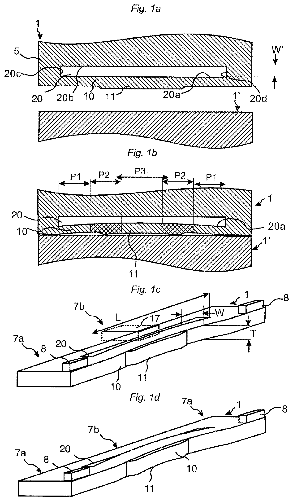
[0126]The embodiments in FIGS. 1a-1d are used to explain some main problems related to flexible locking elements made in one piece with a core and some basic principles of the inventive concept.

[0127]Locking systems comprising flexible and bendable parts formed in one piece with the core are to a major extent dependent of the material properties and thickness of the core that may vary between various core materials and between the same type of core materials. Each locking system must be formed with a specific geometry that is optimized in relation to the properties and thickness of the specific floor panel. This means that a locking system must provide a variety of alternative geometries and principles that could be combined in order to meet the requirements of normal tolerances used in a cost efficient high speed production, locking strength, easy and reliable installation. The inventive concept provides several principles that may be combined and may be used to form a locking syst...


PUM

PropertyMeasurementUnit
thickaaaaaaaaaa
thickaaaaaaaaaa
thickaaaaaaaaaa

Abstract

Floor panels are shown, which are provided with a mechanical locking system that may be locked with a vertical displacement of a first panel against a second panel. The locking system includes a first rigid and a second flexible joint edge section with different locking functions. The first edge section provides a horizontal locking and the second section provides a vertical locking.

Description

TECHNICAL FIELD[0001]The disclosure generally relates to the field of mechanical locking systems for floor panels and building panels. The disclosure shows floorboards, furniture components, locking systems and production methods.FIELD OF APPLICATION OF THE INVENTION[0002]Embodiments of the present invention are particularly suitable for use in floating floors, which are formed of floor panels having of one or more upper layers comprising, e.g., thermoplastic or thermosetting material or wood veneer, an intermediate core of wood-fibre-based material or plastic material and preferably a lower balancing layer on the rear side of the core. Embodiments of the invention can also be used for joining building panels which preferably contain a board material for instance wall panels, ceilings, furniture components and similar.[0003]The following description of prior-art technique, problems of known systems and objects and features of the invention will therefore, as a non-restrictive exampl...

Claims


Application Information

Patent Timeline
Patent Type & Authority Patents(United States)
IPC IPC(8): E04F15/02E04F15/10
CPCE04F15/102E04F15/02038E04F2201/0138E04F2201/0123E04F2201/0146E04F2201/041E04F2201/021
Inventor PERVAN, DARKO
Owner CERALOC INNOVATION AB
Why Eureka
Try Eureka