Electric connector

a technology of electric connectors and connectors, applied in the direction of electrical apparatus, connection, coupling device connection, etc., can solve the problem of weak lock strength, and achieve the effect of large lock strength

Active Publication Date: 2016-03-15
ACES ELECTRONICS CO LTD
View PDF78 Cites 17 Cited by
  • Summary
  • Abstract
  • Description
  • Claims
  • Application Information

AI Technical Summary

Benefits of technology

[0009]According to the present invention, an electric connector having large lock strength can be provided.

Problems solved by technology

However, in the above electric connectors, the housings are made of a resin, and thus the housings are worn away due to repetitive insertion and removal of the connectors, and lock strength becomes weak.

Method used


Image

  • Electric connector
  • Electric connector
  • Electric connector

Examples


Embodiment Construction

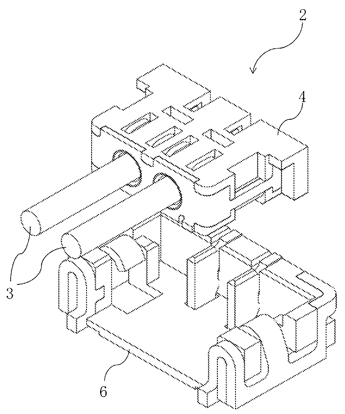
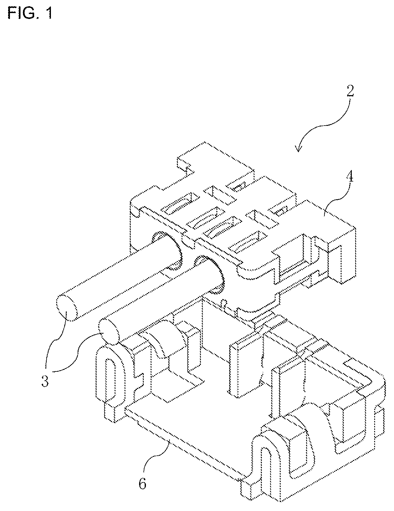
[0017]An electric connector according to an embodiment of the present invention will be herein described with reference to the drawings. FIG. 1 is a perspective view of an electric connector according to an embodiment. As illustrated in FIG. 1, an electric connector 2 includes an electric wire-side connector 4 connected to electric wires 3, and a board-side connector 6 mounted on a circuit board surface (not illustrated).

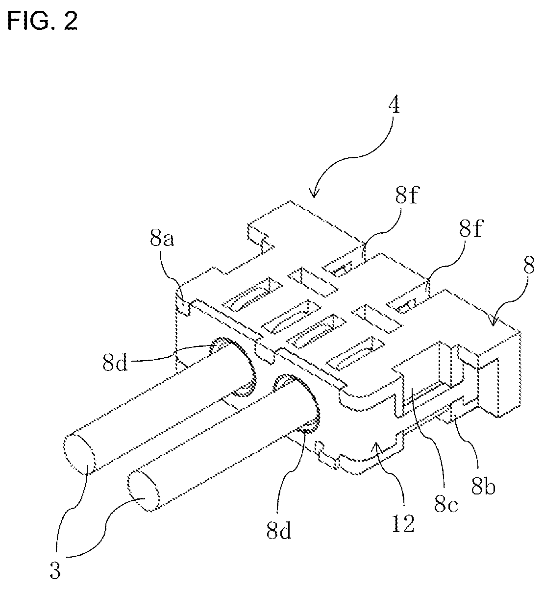
[0018]FIG. 2 is a perspective view of the electric wire-side connector 4 as viewed from above, and FIG. 3 is a perspective view of the electric wire-side connector 4 as viewed from below. As illustrated in FIGS. 2 and 3, the electric wire-side connector 4 includes a rectangular parallelepiped housing 8 inserted into the board-side connector 6 in a direction (hereinafter, referred to as board perpendicular direction) perpendicular to the circuit board surface. Here, the housing 8 is formed of a resin member having insulation properties.

[0019]Further, a plurality of e...


PUM


Abstract

An electric connector includes a first connector, and a second connector, wherein the first connector includes a first housing, a plurality of first contacts, and first lock metal fittings, the second connector includes a second housing, a plurality of second contacts, and a second lock metal fitting, an electric wires are inserted into the second connector in a direction parallel to a circuit board surface, and in a direction perpendicular to an arranging direction of the second contacts, and the second lock metal fitting includes lock engaging portions provided at both ends of the arranging direction of the second contacts of the second housing, and a coupling portion coupling the lock engaging portions at least at a side of a removing direction of the second connector of the electric wires at an insertion side of the electric wires of the second housing.

Description

CROSS-REFERENCE TO RELATED APPLICATIONS[0001]This application claims priority to Japanese Patent Application No. 2013-171060, filed on Aug. 21, 2013, which is incorporated herein by reference in its entirety.BACKGROUND OF THE INVENTION[0002]The present invention relates to an electric connector that connects an electric wire and a board.[0003]Typically, there are electric connectors including a base connector including a resin housing mounted on a circuit board, and a socket connector including a resin housing fit into the base connector in a direction perpendicular to the circuit board (e.g., see JP 2006-128033 A). According to the electric connectors, the socket connector can be locked in the base connector by use of friction between the housings.[0004]However, in the above electric connectors, the housings are made of a resin, and thus the housings are worn away due to repetitive insertion and removal of the connectors, and lock strength becomes weak.SUMMARY OF THE INVENTION[0005...

Claims


Application Information

Patent Timeline
Patent Type & Authority Patents(United States)
IPC IPC(8): H01R12/75H01R12/71H01R13/627
CPCH01R12/75H01R12/716H01R13/6275
Inventor YOSHIDA, NORIO
Owner ACES ELECTRONICS CO LTD
Why Eureka
Try Eureka