Spinal Implant Connection Assembly

a technology of spinal implants and connection assemblies, applied in the field of spinal implant connection assemblies, can solve the problems of difficult to obtain a secure connection between the elongated rod and the bone anchorage, and achieve the effect of increasing the locking strength of the connection assembly

Active Publication Date: 2010-09-16
GLOBUS MEDICAL INC
View PDF29 Cites 18 Cited by
  • Summary
  • Abstract
  • Description
  • Claims
  • Application Information

AI Technical Summary

Benefits of technology

[0005]The present invention provides a connection assembly that can be used to securely connect a spinal implant to a bone anchor. In particular, the present invention preferably provides a connection assembly that is able to securely connect the spinal implant to the anchor even when there is a variance in the angle and position of the anchor with respect to the spinal implant. Furthermore, in an embodiment of the present invention, the connection assembly provides additional structure to increase the locking strength of the connection assembly.

Problems solved by technology

As a result, it can be difficult to obtain a secure connection between the elongated rod and the bone anchors.

Method used


Image

  • Spinal Implant Connection Assembly
  • Spinal Implant Connection Assembly

Examples


Embodiment Construction

[0011]The following description of the preferred embodiment(s) is merely exemplary in nature and is in no way intended to limit the invention, its application, or uses.

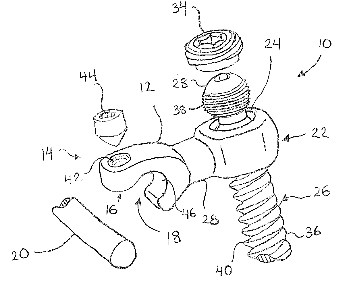
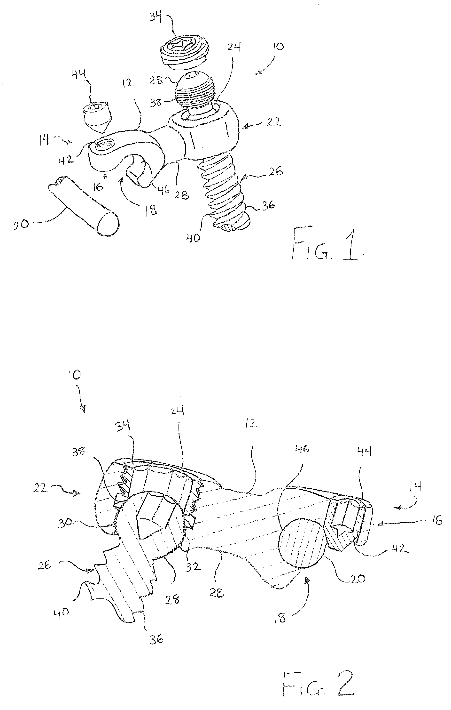
[0012]With reference to FIGS. 1-2, a first embodiment of a connection assembly 10 is illustrated. The connection assembly 10 preferably includes a housing member 12 having, at a first end 14, a generally hook shaped end portion 16 defining a channel 18 configured and dimensioned for receiving at least a portion of a spinal implant 20, such as a spinal rod. At a second end 22, the housing member 12 includes a first opening 24 for receiving at least a portion of an anchor 26, such as a bone screw. The first end 14 and the second end 22 of the housing member 12 are joined by an elongated neck portion 28. The neck portion 28 preferably integrally joins the first end 14 and the second end 22 to form a unitary, one-piece housing member 12.

[0013]In an exemplary embodiment, the first opening 24 is configured and dimensioned t...


PUM


Abstract

The present invention provides a connection assembly that can be used to securely connect a spinal implant to a bone anchor. In particular, the present invention preferably provides a spinal implant connection assembly that is able to securely connect the spinal implant to the anchors even when there is a variance in the angle and position of the anchors with respect to the spinal implant. Furthermore, the present invention provides a connection assembly with structure to increase the locking strength of the connection assembly.

Description

FIELD OF THE INVENTION[0001]The present invention relates generally to a connection assembly, and more particularly, to a variable angle spinal implant connection assembly.BACKGROUND OF THE INVENTION[0002]Spinal deformities, spinal injuries, and other spinal conditions may be treated with the use of spinal implants. Spinal implants are designed to support the spine and properly position the components of the spine. One such spinal implant includes an elongated rod and a plurality of bone anchors. The elongated rod is positioned to extend along one of more of the components of the spine and the bone anchors are attached to the spinal components at one end and secured to the elongated rod at the other end.[0003]However, due to the anatomical structure of the patient, the spinal condition being treated, and, in some cases, surgeon preference, the bone anchors may be required to be positioned at various angles from the elongated rod. In addition, depending on the location of the bone an...

Claims


Application Information

Patent Timeline
Patent Type & Authority Applications(United States)
IPC IPC(8): A61B17/70
CPCA61B17/7041A61B17/7035
Inventor IOTT, ANDREWFRIEDRICH, ADAMCAHILL, DOUGLASJUCHNO, BRAD
Owner GLOBUS MEDICAL INC
Why Eureka
Try Eureka