Board mounting type connector with metal fastening member

a technology of metal fastening member and mounting type, which is applied in the direction of connection effected by permanent deformation, coupling device connection, printed circuit, etc., can solve the problems of deteriorating workability, difficult to properly design and manufacture the housing of the connector, and difficult to properly confirm the complete fit state. , to achieve the effect of effectively miniaturizing the connector, improving workability, and improving lock feeling

Inactive Publication Date: 2007-08-21
AUTONETWORKS TECH LTD +2
View PDF7 Cites 17 Cited by
  • Summary
  • Abstract
  • Description
  • Claims
  • Application Information

AI Technical Summary

Benefits of technology

[0009]It is an object of the invention to provide a board mounting type connector which can be reliably miniaturized and in which a engaging portion having sufficient locking strength can be properly and simply formed.
[0025]According to the above-aspects of the invention, since the completely fitted state of the housings can be confirmed through sound or vibration (clash feeling) which is generated when the elastic member returns to its original unbent state, the lock feeling can be improved. Therefore, it is possible to effectively miniaturize the connectors and improve workability when fitting the connectors with each other.

Problems solved by technology

In this type of connectors, for example, applied to various electric instruments provided on a motor vehicle, as miniaturization of the connectors is required to meet increasing demand toward improvement of efficiency of space utilization, the following problems have been caused.
However, as the housings of the connectors are miniaturized, the positions or sizes of the engaging portions cannot but be limited, whereby it is difficult to properly design and manufacture the housings of the connectors in consideration of a relationship with molds.
Therefore, it is difficult to properly confirm the completely fitted state, whereby workability deteriorates.

Method used


Image

  • Board mounting type connector with metal fastening member
  • Board mounting type connector with metal fastening member
  • Board mounting type connector with metal fastening member

Examples


Embodiment Construction

[0043]Hereinafter, a board mounting type connector according to a preferred embodiment of the invention will be described with reference to accompanying drawings.

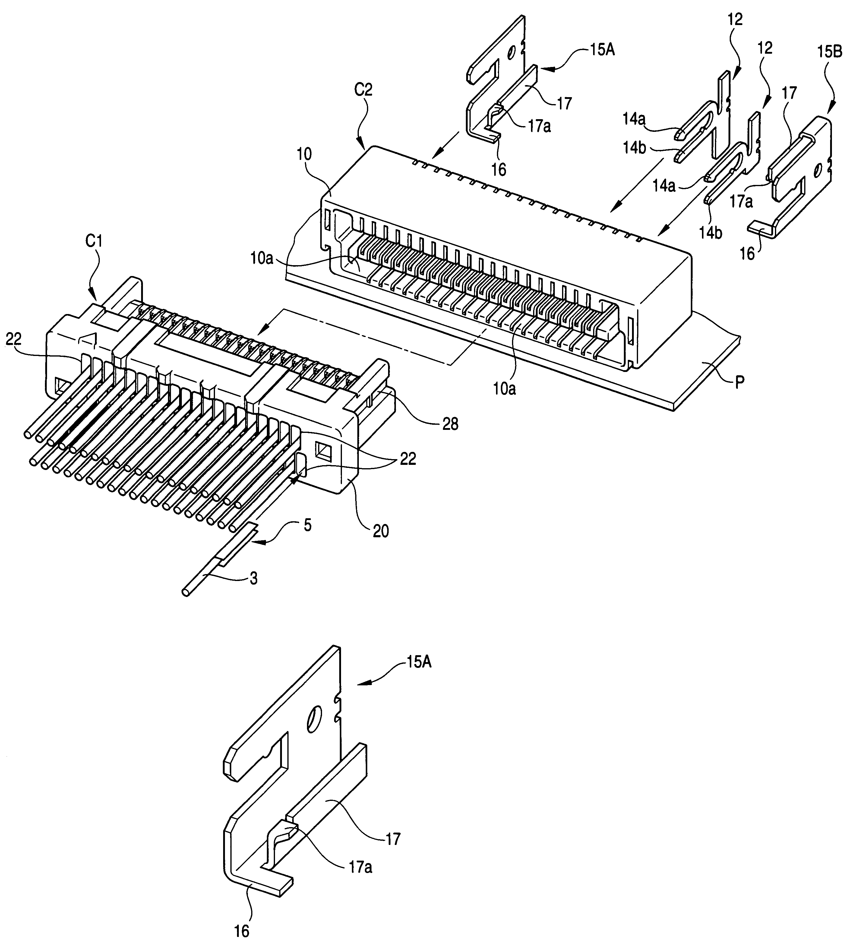
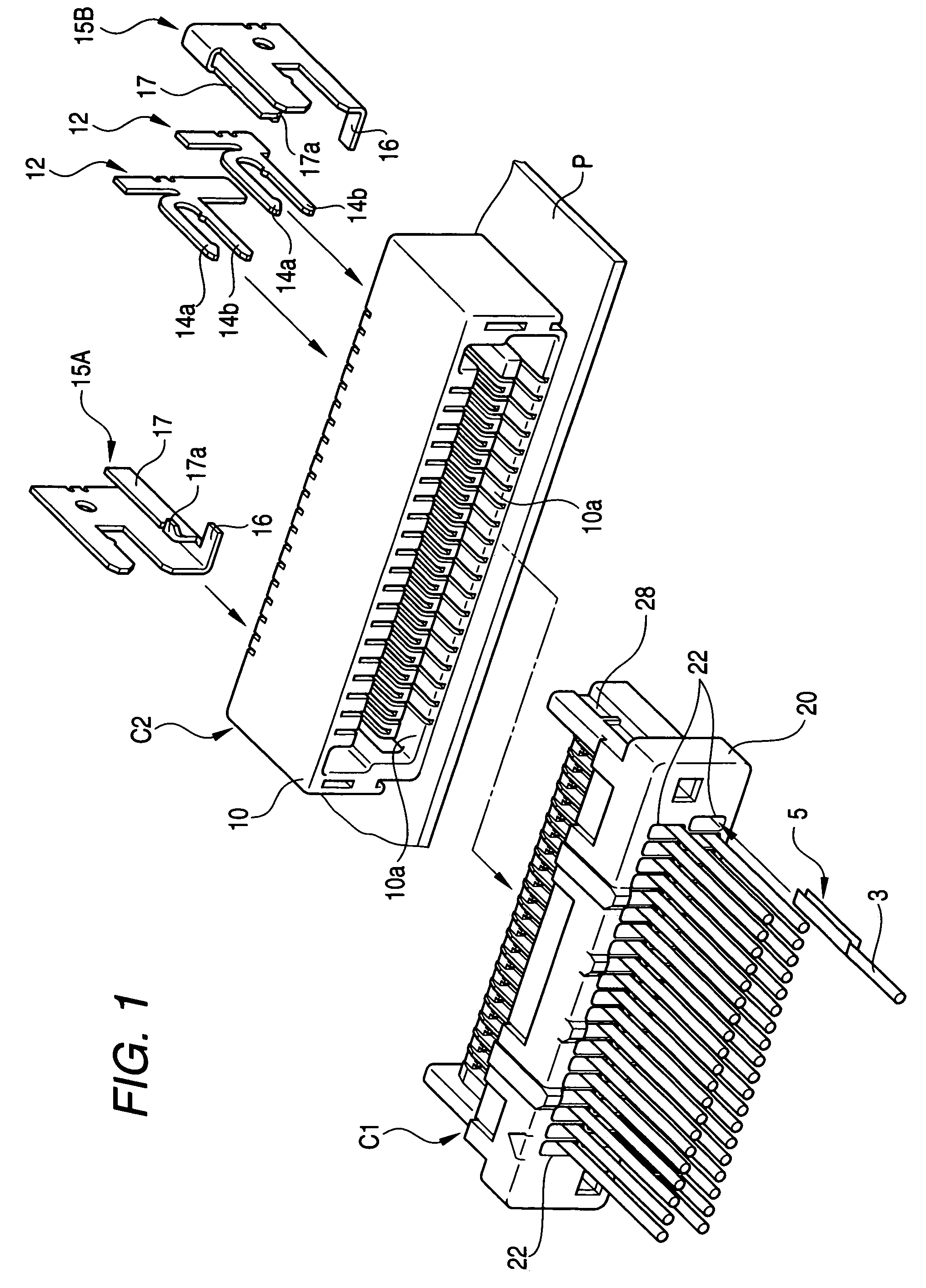
[0044]FIG. 1 is a perspective view schematically illustrating the construction of a connector for electrically connecting discrete wires to a circuit board. In FIG. 1, a terminal and some components are illustrated in a disassembled state.

[0045]In FIG. 1, the reference numeral C2 indicates a board-side connector that corresponds to a board mounting type connector according one embodiment. The board-side connector C2 is fixedly maintained in a state in which it is mounted on the surface of a circuit board P. Also, the reference numeral C1 indicates a wiring material-side connector. The wiring material-side connector C1 is structured to connect discrete wires 3 to the circuit board P by being coupled to the board-side connector C2.

[0046]The board-side connector C2 includes a connector housing 10 (hereinafter, referred to as a...


PUM


Abstract

A board mounting type connector includes: a housing being made of a resin, the housing holding a plurality of terminals, each terminal being arranged in parallel and connected to a circuit board; and a metal fastening member being fixed to both ends of the housing in a widthwise direction of the housing in which the terminals are arranged, the metal fastening member being mounted to the circuit board, and each metal fastening member having an engaging portion which engages with a housing of a counterpart connector fitted into the board mounting type connector so that the connectors are engageable to each other in a fitted state.

Description

BACKGROUND OF THE INVENTION[0001]1. Field of the Invention[0002]The present invention relates to a board mounting type connector which is mounted to a circuit board.[0003]2. Description of the Related Art[0004]In a related art, a connector connection structure has been disclosed. In this structure, a female connector is configured such that each of male terminals is mounted to the distal end of each of discrete wires and is received in each of a plurality of terminal-receiving cavities which are formed in parallel in a housing of the female connector, and a male connector (a board mounting type connector) is configured such that a housing of the male connector which receives female terminals is mounted to a printed circuit board. The discrete wires can be electrically connected to a circuit on the printed circuit board through the male and female terminals by coupling the female and male connectors to each other.SUMMARY OF THE INVENTION[0005]In this type of connectors, for example, ...

Claims


Application Information

Patent Timeline
Patent Type & Authority Patents(United States)
IPC IPC(8): H01R13/627H01R4/18
CPCH01R12/707H01R13/6275
Inventor TANAKA, TETSUJIHIRAI, HIROKITAMAGAWA, TATSUOHIRAMITSU, HIROOMISAKAI, YOSHITO
Owner AUTONETWORKS TECH LTD
Why Eureka
Try Eureka