Laser wave combination apparatus

A laser and laser technology, which is applied in the field of laser multiplexing devices, can solve the problems of difficult manufacturing and difficult manufacturing of redirection systems.

Inactive Publication Date: 2009-06-24
ADTEC ENG
View PDF9 Cites 0 Cited by
  • Summary
  • Abstract
  • Description
  • Claims
  • Application Information

AI Technical Summary

Problems solved by technology

[0020] As mentioned above, while the position of the redirecting system is fixed at a very small area where multiple beam waists are concentrated with high precision, it is necessary to make the redirecting system itself consistent with the shape of each beam at the above-mentioned focusing position, and to carry out a compact operation. Moreover, it is produced with high precision, and the manufacture of the redirection system is difficult
In addition, since the size of the beam waist is proportional to the wavelength, in recent years, with the shortening of the wavelength of the laser light source, the above-mentioned size has been reduced, and the high-precision fixing and miniaturization of the redirection system are more required, and the manufacturing difficulty is becoming more and more difficult.

Method used


Image

  • Laser wave combination apparatus
  • Laser wave combination apparatus
  • Laser wave combination apparatus

Examples


Embodiment 1-1

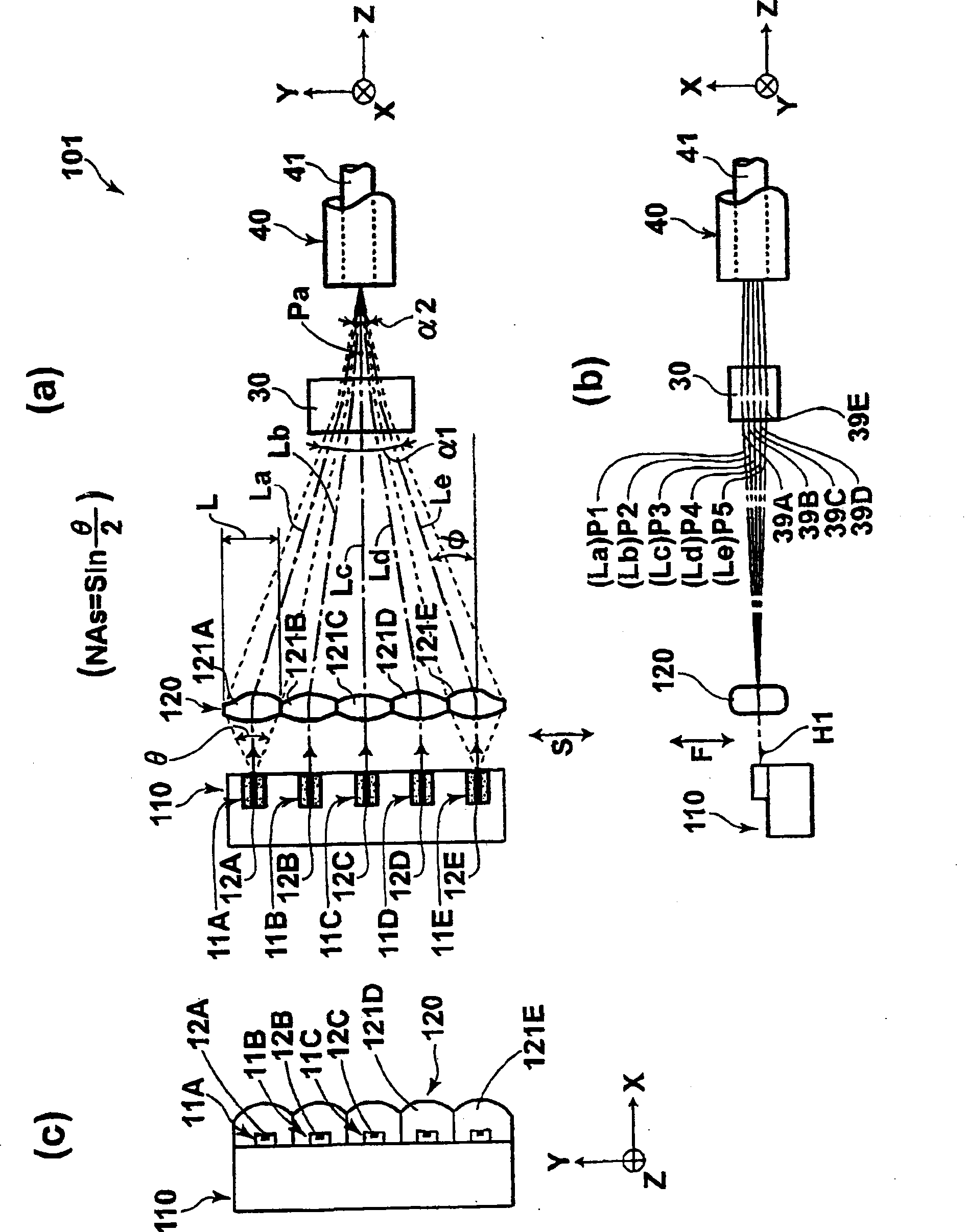
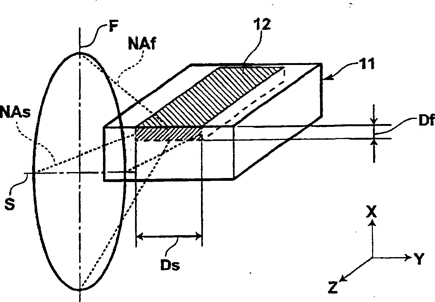
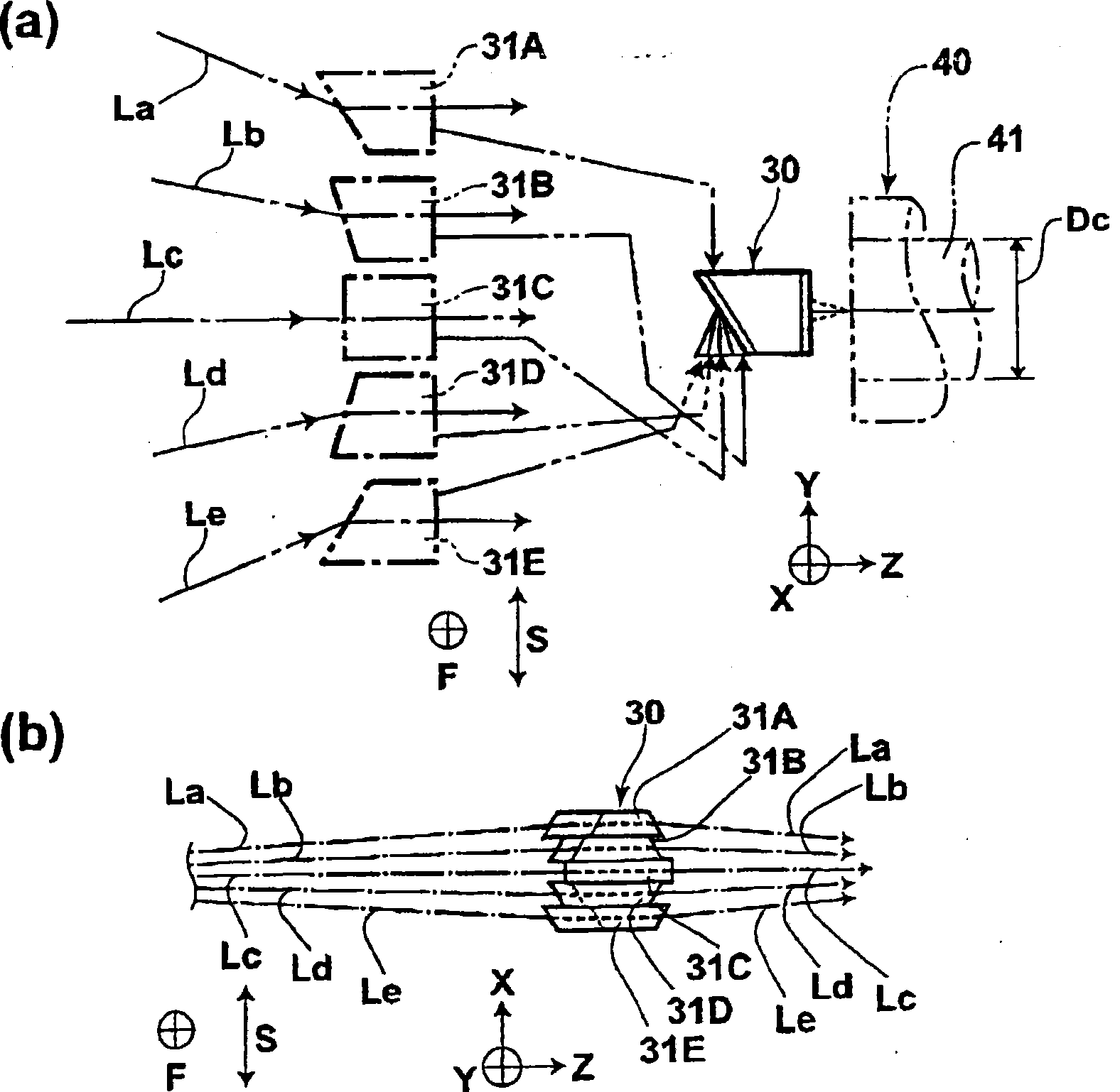
[0123] figure 1 It is a schematic configuration diagram of a laser multiplexing device showing a first example (hereinafter referred to as Example 1-1) in the first embodiment of the present invention, figure 1 (a) is the plan view that observes above-mentioned laser multiplexing device from above, figure 1 (b) is a front view of observing the above-mentioned laser multiplexing device from the direction in which the semiconductor lasers are arranged, figure 1 (c) is a left side view of the above-mentioned laser multiplexing device viewed from the direction of the optical axis of the light beam. in addition, figure 2 It is a perspective view showing a state where a laser beam is emitted from an active layer of a semiconductor laser, image 3 It is a state diagram showing the structure of the focusing angle conversion optical system and the beams multiplexed in the optical fiber through the focusing angle conversion optical system, image 3 (a) is a plan view showing th...

Embodiment 1-2

[0138] Hereinafter, a laser multiplexing device of a second example (hereinafter referred to as example 1-2) in the first embodiment of the present invention will be described. Figure 5 is a schematic configuration diagram showing the above-mentioned laser multiplexing device, Figure 5 (a) is a top view of the laser combining device observed from above, Figure 5 (b) is a top view of the laser multiplexing device observed from the direction in which the semiconductor lasers are arranged, Figure 5 (c) is a left side view of the laser multiplexing device observed from the optical axis direction of the beam, Figure 6 is a functional diagram showing the deflection of light beams by individual lenses constituting the deflection lens, Figure 6 (a) is a schematic diagram of the above-mentioned individual lens viewed with the Y direction as the upper side of the paper, Figure 6 (b) is a schematic diagram of the above-mentioned individual lenses viewed with the X direction as ...

Embodiment 2-1

[0157] Figure 9 It is a schematic configuration diagram showing the laser multiplexing device 201 of the first example (hereinafter referred to as Example 2-1) in the second embodiment of the present invention, Figure 9 (a) is the plan view that observes above-mentioned laser multiplexing device from above, Figure 9 (b) is a front view of observing the above-mentioned laser multiplexing device from the laser arrangement direction, Figure 9 (c) is to observe above-mentioned laser multiplexing device figure from the optical axis direction of light beam, Figure 10 It is a diagram showing a state in which the focusing angle conversion optical system converges the optical axes of the respective light beams parallel to each other in the slow-axis direction view. Such as Figure 9 As shown, the laser multiplexing device 201 of the embodiment 2-1 includes the laser block 10, all the focusing optical systems 20, and the focusing angle conversion optical system 30C.

[0158] In...


PUM

PropertyMeasurementUnit
wavelengthaaaaaaaaaa
diameteraaaaaaaaaa
diameteraaaaaaaaaa

Abstract

PURPOSE: A laser multiplexing apparatus for causing an entire bundle of light beams emitted from plural semiconductor lasers to enter an optical fiber is provided to acquire laser beams having high energy density by using the entire bundle of the light beams emitted from the plural semiconductor lasers. CONSTITUTION: A laser multiplexing apparatus includes a plurality of semiconductor lasers(11A-11E) in order to offset plural beams emitted from the semiconductor laser diodes to different positions and allow the plural light beams to enter an end side of an optical fiber(40) by converging the plural light beams in a direction of fast axes and in a direction of slow axes of the light beams. The laser multiplexing apparatus further includes an incident angle conversion optic system. The angular conversion optic system converges a bundle of the light beams in the directions of the fast axes and the slow axes of the light beams and allows the converged bundle of the light beams to enter the optical fiber.

Description

technical field [0001] The present invention relates to a laser multiplexing device, and more specifically, to a laser multiplexing device for converging all beams composed of laser beams emitted from a plurality of semiconductor lasers and incident on an optical fiber. Background technique [0002] Conventionally, each beam of laser light emitted by a plurality of semiconductor lasers arranged in one direction is passed through a collimator lens to become a parallel beam with mutually parallel optical axes arranged in one direction, so that the beams arranged side by side A method is well known in which all the light is collected, incident on a single optical fiber, and laser light having a high energy density is transmitted through the optical fiber (for example, Patent Document 1). [0003] In the above-mentioned method, the efficiency (coupling efficiency) when each beam of laser light emitted from a plurality of semiconductor lasers is combined into one optical fiber is...

Claims


Application Information

Patent Timeline
Patent Type & Authority Patents(China)
IPC IPC(8): G02B27/10G02B27/30H01S3/00G02B6/42H01S5/00
CPCE04B1/30E04C3/29E04C5/07
Inventor 山中英生冈崎洋二
Owner ADTEC ENG
Why Eureka
Try Eureka