Semi-active cab suspension assembly method

a cab and suspension technology, applied in the field of agricultural vehicles, can solve the problems of reducing ride quality and operator comfort, cab to jiggle, cab to rotate from side to side, cab to vertical jiggle, etc., to achieve the effect of maximizing the rigidity of the anti-roll bar system, reducing labor and assembly time, and reducing the overall production cost of the vehicl

Active Publication Date: 2020-05-14
INC BLUE LEAF I
View PDF0 Cites 1 Cited by
  • Summary
  • Abstract
  • Description
  • Claims
  • Application Information

AI Technical Summary

Benefits of technology

[0007]In one exemplary embodiment formed in accordance with the present invention, there is provided an agricultural vehicle with a chassis, a cab, and a cab suspension system. The cab suspension system includes an anti-roll bar, main support brackets, and intermediary placement brackets. During assembly of the agricultural vehicle, the anti-roll bar can be positioned on the intermediary placement brackets such that the anti-roll bar is first located in its final assembly position before installing the main support brackets and subsequently securing the anti-roll bar onto the main supports. Hence, the intermediary placement brackets allow the anti-roll bar to be positioned before installing the other components of the agricultural vehicle, thereby making the assembly of the cab suspension system less labor intensive and more efficient.
[0011]One possible advantage of the exemplary embodiment of the cab suspension system is that an anti-roll bar may be positioned in its final assembly position first before installing the other components of the vehicle, which in turn reduces labor, assembly time, and the overall production cost of the vehicle.
[0012]Another possible advantage of the exemplary embodiment of the cab suspension system is that suspension performance may be augmented because the intermediary placement brackets and main support brackets help to maximize the rigidity of the anti-roll bar system.

Problems solved by technology

As the vehicle traverses a field or roadway, vibrational and / or impact forces may be imparted from the chassis to the cab, which in turn reduces ride quality and operator comfort.
Such forces may cause the cab to jounce, rotate from side to side and / or front to back, or vibrate.
For example, impact forces resulting from the wheels traveling over undulations in the field may cause the cab to vertically jounce.
Hence, the forces transmitted to the cab during normal operation of the vehicle may lead to a diminished ride quality as well as operator discomfort and fatigue.
The cab suspension system and the assembly thereof may be limited by the narrow spacing between the cab and the chassis.
For instance, numerous components may need to be fitted within this compact area, which then restricts the various kinds of support mounts, compression springs, or linkages that may be used to support the cab.
Furthermore, certain parts of the cab suspension system may need to be intricately fitted relative to various other components of the vehicle.
Hence, the assembly of the cab suspension system may be time-consuming and costly.

Method used


Image

  • Semi-active cab suspension assembly method
  • Semi-active cab suspension assembly method
  • Semi-active cab suspension assembly method

Examples


Embodiment Construction

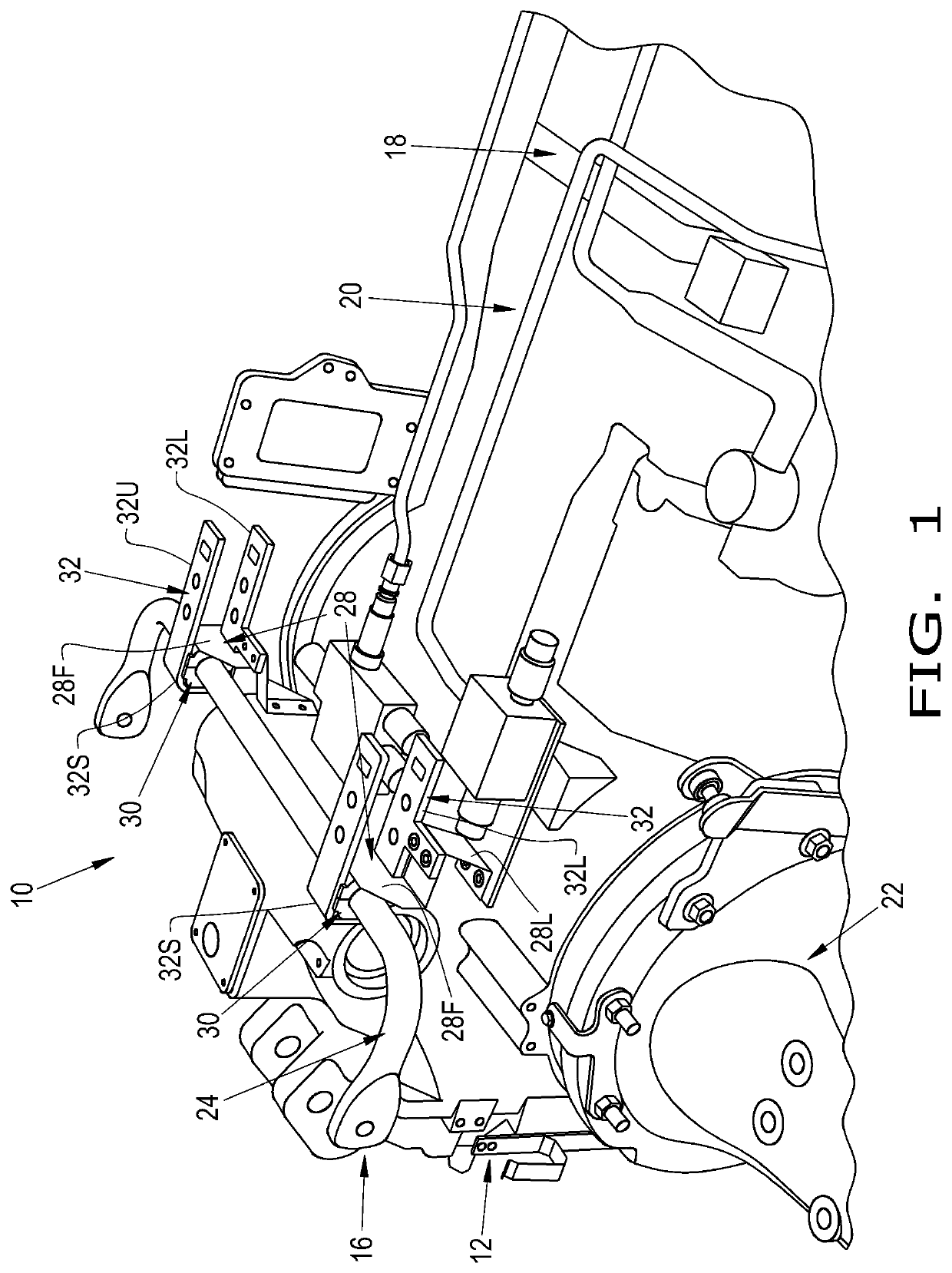
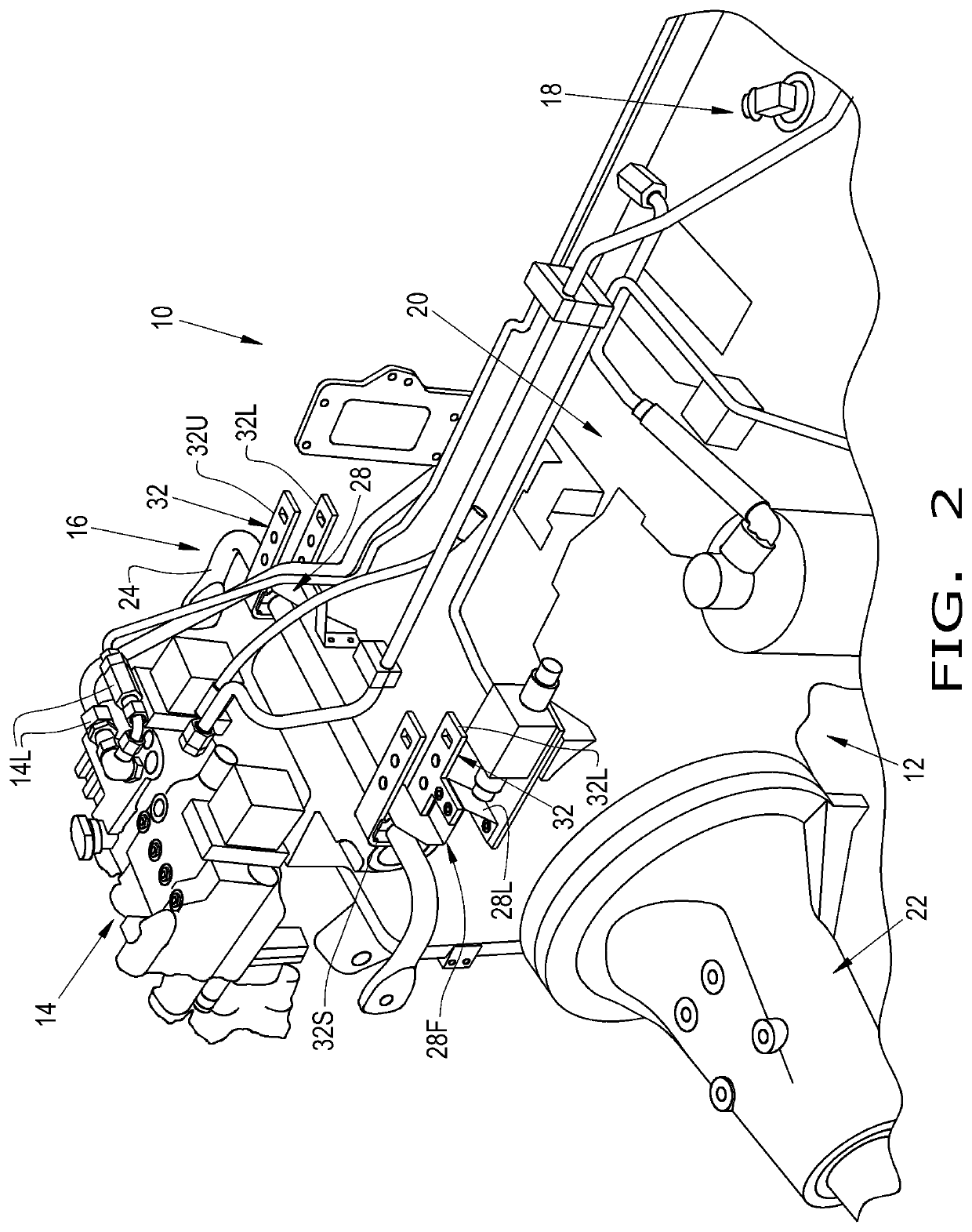
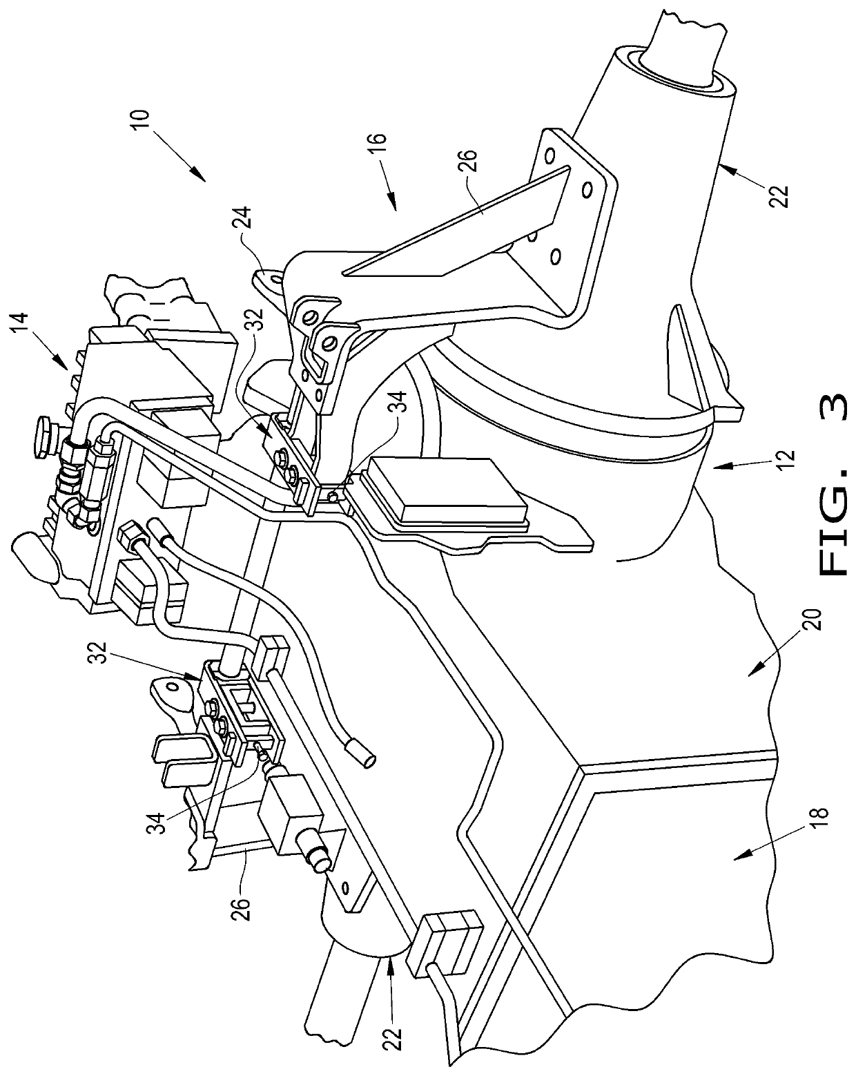
[0018]The terms “forward”, “rearward”, “left” and “right”, when used in connection with the agricultural vehicle and / or components thereof are usually determined with reference to the direction of forward operative travel of the agricultural vehicle, but again, they should not be construed as limiting. The terms “longitudinal” and “transverse” are determined with reference to the fore-and-aft direction of the agricultural vehicle and are equally not to be construed as limiting.

[0019]Referring now to the drawings, and more particularly to FIGS. 1-3, there is shown an exemplary embodiment of an agricultural vehicle 10. As shown, the agricultural vehicle 10 is in the form of a tractor, such as a Case IH Magnum™ series Cash-Crop-High (CCH) tractor. However, the agricultural vehicle 10 may be in the form of any desired industrial or agricultural vehicle, such as a combine, backhoe, crane, dozer, skidsteer loader, etc. The agricultural vehicle 10 generally includes a frame 12, e.g. a chas...


PUM


Abstract

A method for assembling an agricultural vehicle including the initial step of providing the agricultural vehicle including a frame, a hydraulic manifold, and a cab suspension system. The cab suspension system includes an anti-roll bar, a pair of support brackets configured for securing the anti-roll bar to the frame, and a pair of intermediary placement brackets configured for temporarily supporting the anti-roll bar in a final assembly position. The method includes the further steps of attaching the intermediary placement brackets onto the frame, positioning the anti-roll bar on the intermediary placement brackets to position the anti-roll bar in the final assembly position, assembling the hydraulic manifold onto the frame, and connecting the support brackets to the frame and the anti-roll bar.

Description

CROSS REFERENCE TO RELATED APPLICATIONS[0001]This is a non-provisional application based upon U.S. provisional patent application Ser. No. 62 / 758,542, entitled “SEMI-ACTIVE CAB SUSPENSION ASSEMBLY METHOD”, filed Nov. 10, 2018, which is incorporated herein by reference.BACKGROUND OF THE INVENTION[0002]The present invention pertains to agricultural vehicles and, more specifically, to a method for assembling a cab suspension system of an agricultural vehicle.[0003]Agricultural or industrial vehicles, such as tractors, combines, backhoes, cranes, or dozers, generally include a chassis, supported by wheels or tracks, a prime mover, and a cab. Large vehicles typically include a cab that is separately assembled as an individual unit and subsequently mounted onto the chassis via support mounts. As the vehicle traverses a field or roadway, vibrational and / or impact forces may be imparted from the chassis to the cab, which in turn reduces ride quality and operator comfort. Since a cab is gene...

Claims


Application Information

Patent Timeline
Patent Type & Authority Applications(United States)
IPC IPC(8): B60G21/055B62D33/06
CPCB60G21/0551B60G2206/601B62D33/06B60G2206/80B60G2206/201B62D33/0617B62D33/0604B60G2204/1222B60G99/002
Inventor PAULSON, THOMAS J.KOCH, LUCASDRAEGER, MARK S.ADUPALA, RAJESHWAR
Owner INC BLUE LEAF I
Why Eureka
Try Eureka