Small form factor, field-installable connector

a field-installable connector and small form factor technology, applied in the field of field-installable connectors, can solve the problems of insufficient space around the splice assembly in the connector for resilient, the structure limitation and the problem of limiting the function of the field-installable connector in the field, so as to reduce the radial dimension of the resilient member and the effect of small form factor

Inactive Publication Date: 2006-01-05
COMMSCOPE TECH LLC
View PDF30 Cites 73 Cited by
  • Summary
  • Abstract
  • Description
  • Claims
  • Application Information

AI Technical Summary

Benefits of technology

[0008] The present invention provides for a spring-loaded, small form factor, field-installable connector by using a space-saving clamping assembly and resilient member coupled with a roomy connector housing. Specifically, in a preferred embodiment, a unique clamping assembly is used which has fewer tapered surfaces and moving parts than those typically used in the prior art. By using fewer moving parts, the clamping assembly is more efficient and lends itself to miniaturization. This clamping assembly is used preferably with an efficient resilient member design which achieves its resilient properties through elastic material which is aligned axially along the connector rather than radially. This reduces the radial dimension of the resilient member. The combination of the unique clamping assembly and the “axial” resilient member provides for a compact “spring-loaded” mechanism within the connector housing. The connector housing, itself, is designed to be roomy through the use of a unitary configuration which avoids the space-consuming two-piece, telescoping design used in the prior art. The result is a compact field-installable connector which has a small form factor and offers a spring-loaded ferrule.

Problems solved by technology

Unfortunately, existing field-installable fiber optic connectors tend to be of the larger connector types such as the industry-standard SC and ST type connectors.
The existing small-form-factor, field-installable connectors are limited in function by their structure.
Although effective in holding the fiber, this splice assembly occupies significant space making its implementation in small form factor connectors problematic.
Specifically, there is not sufficient space around the splice assembly in the connector for resilient means to bias the ferrule forward.
Indeed, applicants are not aware of any field-installable, small-form-factor connectors that have a spring-loaded ferrule.
They are unsuited for mating with fixed interface, non spring-loaded devices such as optical transceivers.

Method used


Image

  • Small form factor, field-installable connector
  • Small form factor, field-installable connector
  • Small form factor, field-installable connector

Examples


Embodiment Construction

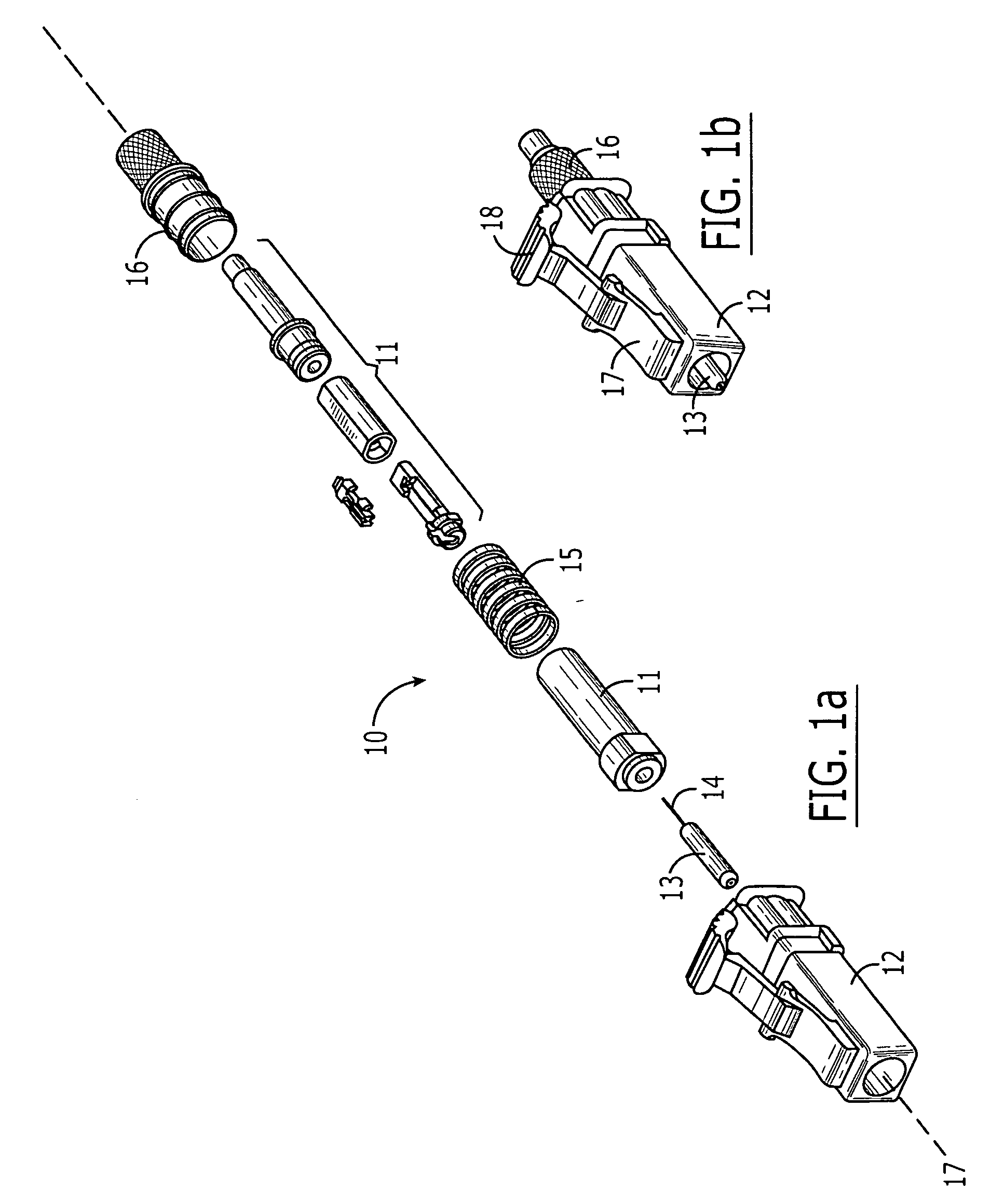
[0021] Referring to FIG. 1a, a preferred embodiment of an LC-type connector 10 comprising a clamping assembly 11 of the present invention is shown in an exploded view. The connector 10 and clamping assembly 11 are described herein with respect to a top / bottom and front / back orientation. It should be understood that reference is made to this orientation for purposes of illustration and to describe the relative position of the components within a given connector. It should be therefore understood that this orientation is not an absolute orientation and that rotating, inverting or otherwise altering the connector's position in space is possible without changing the relative position of the components of the connector. Additionally, the connector 10 has at least one optical axis 17. The optical axis 17 corresponds to the axis along which light propagates in the terminated connector. It should be understood that the connector may have more than one optical axis if the connector is used t...


PUM


Abstract

A small form factor, field-installable optical connector comprising: (a) a small form factor connector housing having a front and back orientation; (b) a ferrule disposed in the connector housing; (c) a clamping assembly disposed in the connector housing rearward of the ferrule and adapted to receive and retain a terminating fiber; (d) a resilient member disposed in the connector housing; and (e) a rear body disposed at the rear end of the connector housing and configured to provide a backstop against which the resilient member can press to bias the ferrule and the clamping assembly forward.

Description

CROSS REFERENCE TO RELATED APPLICATIONS [0001] This application claims priority to U.S. Provisional Application No. 60 / 584,367, filed Jun. 30, 2004, which is hereby incorporated in its entirety.FIELD OF INVENTION [0002] The present invention relates generally to a field installable connector, and, more specifically, to a small form factor, field-installable connector. BACKGROUND [0003] Optical fiber connectors are an essential part of practically all optical fiber communication systems. For instance, such connectors are used to join segments of fiber into longer lengths, to connect fiber to active devices such as radiation sources, detectors and repeaters, and to connect fiber to passive devices such as switches and attenuators. The principal function of an optical fiber connector is to optically couple a fiber with the mating device (e.g., another fiber, an active device or a passive device) by holding the end of the fiber such that the core of the fiber is axially aligned with the...

Claims


Application Information

Patent Timeline
Patent Type & Authority Applications(United States)
IPC IPC(8): G02B6/36
CPCG02B6/3806G02B6/3846G02B6/3833G02B6/3821
Inventor MANNING, RANDY MARSHALLERDMAN, DAVID DONALDGURRERI, MICHAEL LAWRENCE
Owner COMMSCOPE TECH LLC
Why Eureka
Try Eureka