Coupling system of a low friction sealing assembly with a bearing ring and a hub bearing unit equipped with such a sealing assembly

Active Publication Date: 2015-06-04
AB SKF
View PDF13 Cites 23 Cited by
  • Summary
  • Abstract
  • Description
  • Claims
  • Application Information

AI Technical Summary

Benefits of technology

[0006]It is the object of the present invention to provide a sealing assembly comprising at least one shield rotating in use having a coupling system of such a shield with a ring rotating in use of a rolling bea

Problems solved by technology

On one hand, this drawback increases the friction on the sealing assembly, because the non-sliding sealing lips (which thus do not generate friction) may become sliding (and thus generate friction), and the possibly sliding sealing lips increase their interference, and thus the generated friction.
On the other h

Method used


Image

  • Coupling system of a low friction sealing assembly with a bearing ring and a hub bearing unit equipped with such a sealing assembly
  • Coupling system of a low friction sealing assembly with a bearing ring and a hub bearing unit equipped with such a sealing assembly
  • Coupling system of a low friction sealing assembly with a bearing ring and a hub bearing unit equipped with such a sealing assembly

Examples


Embodiment Construction

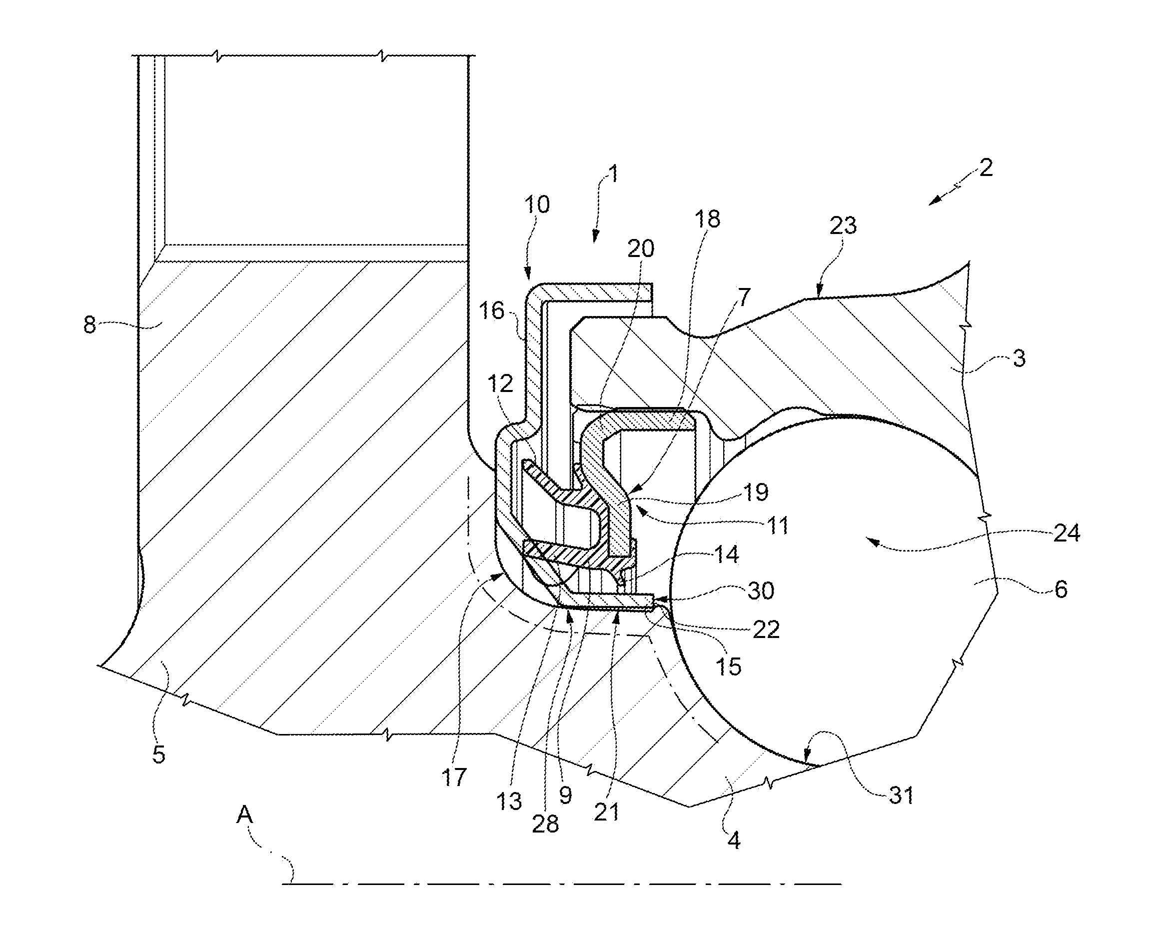
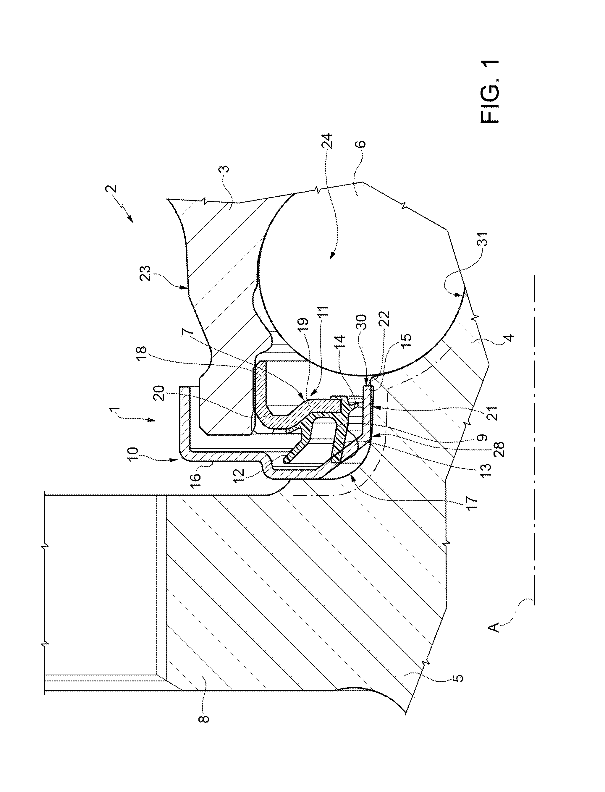
[0024]With reference to FIG. 1, reference numeral 1 indicates a low friction sealing assembly, in particular designed to be mounted on a hub bearing unit 2 of a vehicle, of which the sealing assembly 1 becomes an integral part in use.

[0025]The hub bearing unit 2 comprises an outer ring 3, stationary in use, an inner ring 4, rotating in use about an axis A, which is also the symmetry axis of both rings 3 and 4 of the sealing assembly 1, and at least one crown of rolling bodies 6 interposed between the outer ring 3 and the inner ring 4, which are mutually coaxial; the ring 4 has an end 5 provided with a flange 8 opposite to the outer ring 3 and intended to carry a wheel of the vehicle in use.

[0026]The sealing assembly 1 can be inserted in an annular gap 7 delimited between the inner ring 4 and the stationary outer ring 3 of the hub bearing unit 2 and, more in general, between the rotating member 4 and the stationary member 3, which are mutually coaxial, of a generic rolling bearing of...


PUM


Abstract

A sealing assembly including at least one first annular shield having a sleeve portion integral in use with a rotating member and a flange portion, which radially and overhangingly extends from the sleeve portion. Preferably, a second annular shield is arranged in front of the first shield with the interposition of an annular seal; wherein the sleeve portion of the first shield is delimited by a conic-truncated lateral mounting surface having a tapering facing so as to have a greater diameter arranged on the side of the flange portion and intended to couple in use with a mounting seat of the rotating member formed by a shallow recess delimited by a conic-truncated bottom wall having the same tapering as the lateral mounting surface and by an axial shoulder which is arranged on the side opposite to the flange portion.

Description

CROSS REFERENCE TO RELATED APPLICATION[0001]This is a National Stage application claiming the benefit of Italy Patent Application Number TO2013A000980 filed on 29 Nov. 2013 (29 Nov. 2013), which is incorporated herein by reference in its entirety.TECHNICAL FIELD OF THE INVENTION[0002]The present invention relates to a coupling system between a member of a low friction sealing assembly, in particular for equipping rolling bearings of hub bearing units for vehicles, and a rotating ring of a rolling bearing belonging to a hub bearing unit and to the hub bearing unit thus equipped.PRIOR ART[0003]The sealing assemblies intended to equip the rolling bearings of hub bearing units on the side of the flange which supports the wheel, called “outboard”, for example, such as those described in U.S. Pat. No. 8,303,190 and in US2012 / 0177315, are formed by “cassette” seals, which include a first and a second annular shield, generally L-shaped in radial section, mounted in front of each other so as...

Claims


Application Information

Patent Timeline
IPC IPC(8): B60B27/00
CPCB60B27/0073B60B2900/212B60B2900/511B60B27/0005F16C2226/16F16C33/783F16C33/805F16C2226/12F16C2326/02F16C33/7879F16C19/184F16C33/7889
Inventor BARBERIS, GIORGIODUCH, DANIELEMORELLO, FAUSTOVULPIO, MARIA CONCETTA
Owner AB SKF
Why Eureka
Try Eureka