Cylinder lock device and engagement release mechanism

a technology of cylinder lock and release mechanism, which is applied in the direction of cylinder locks, building locks, construction, etc., can solve the problems of radially scaling up of the lock device, and achieve the effect of increasing the engagement release mechanism in the vehicl

Inactive Publication Date: 2007-09-13
KK TOKAI RIKA DENKI SEISAKUSHO
View PDF9 Cites 22 Cited by
  • Summary
  • Abstract
  • Description
  • Claims
  • Application Information

AI Technical Summary

Benefits of technology

[0046] As described above, according to the invention, the radial miniaturization can be realized. As a result, for example, a degree of freedom...

Problems solved by technology

As a result, there is encountered such a proble...

Method used


Image

  • Cylinder lock device and engagement release mechanism
  • Cylinder lock device and engagement release mechanism
  • Cylinder lock device and engagement release mechanism

Examples


Embodiment Construction

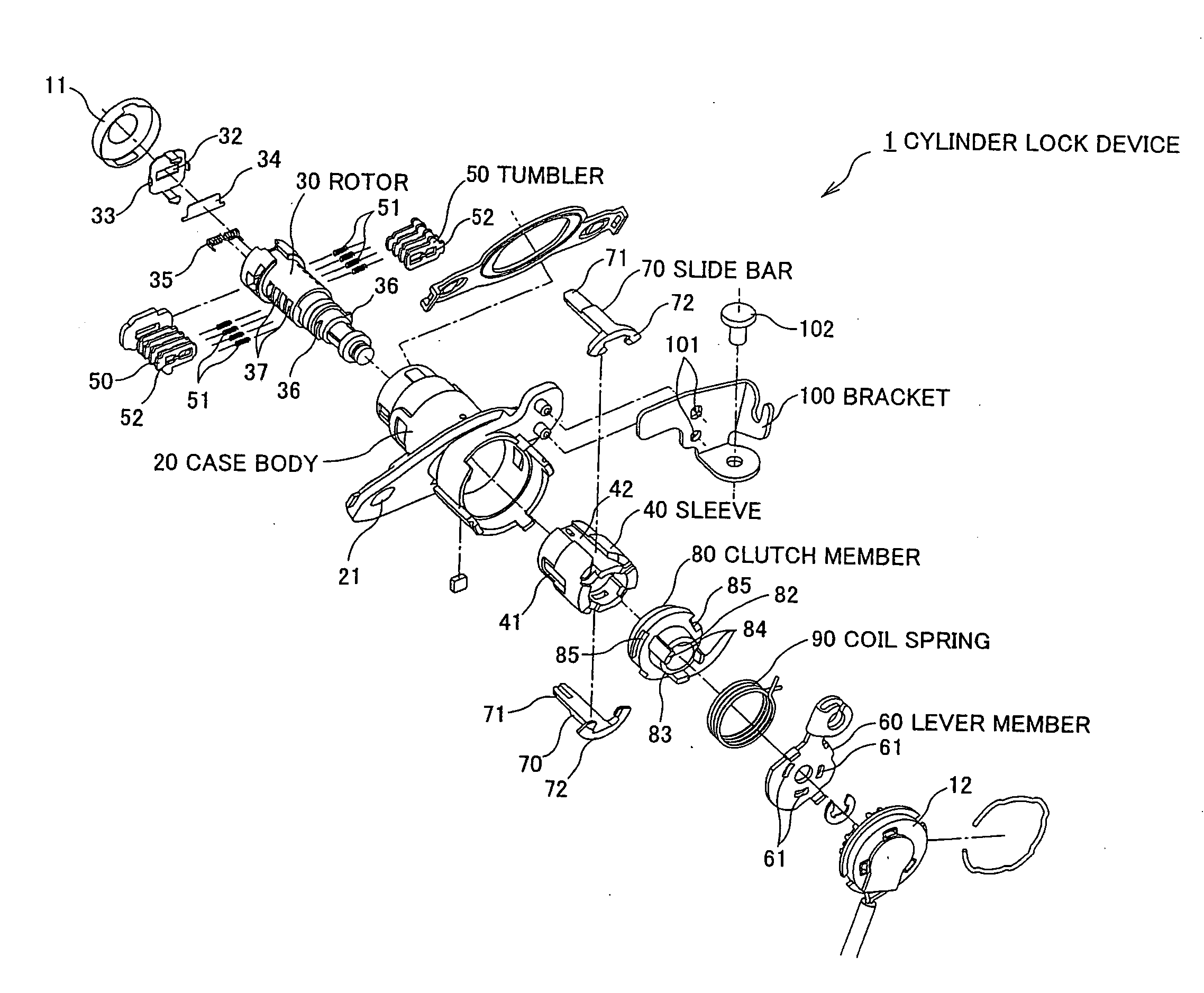
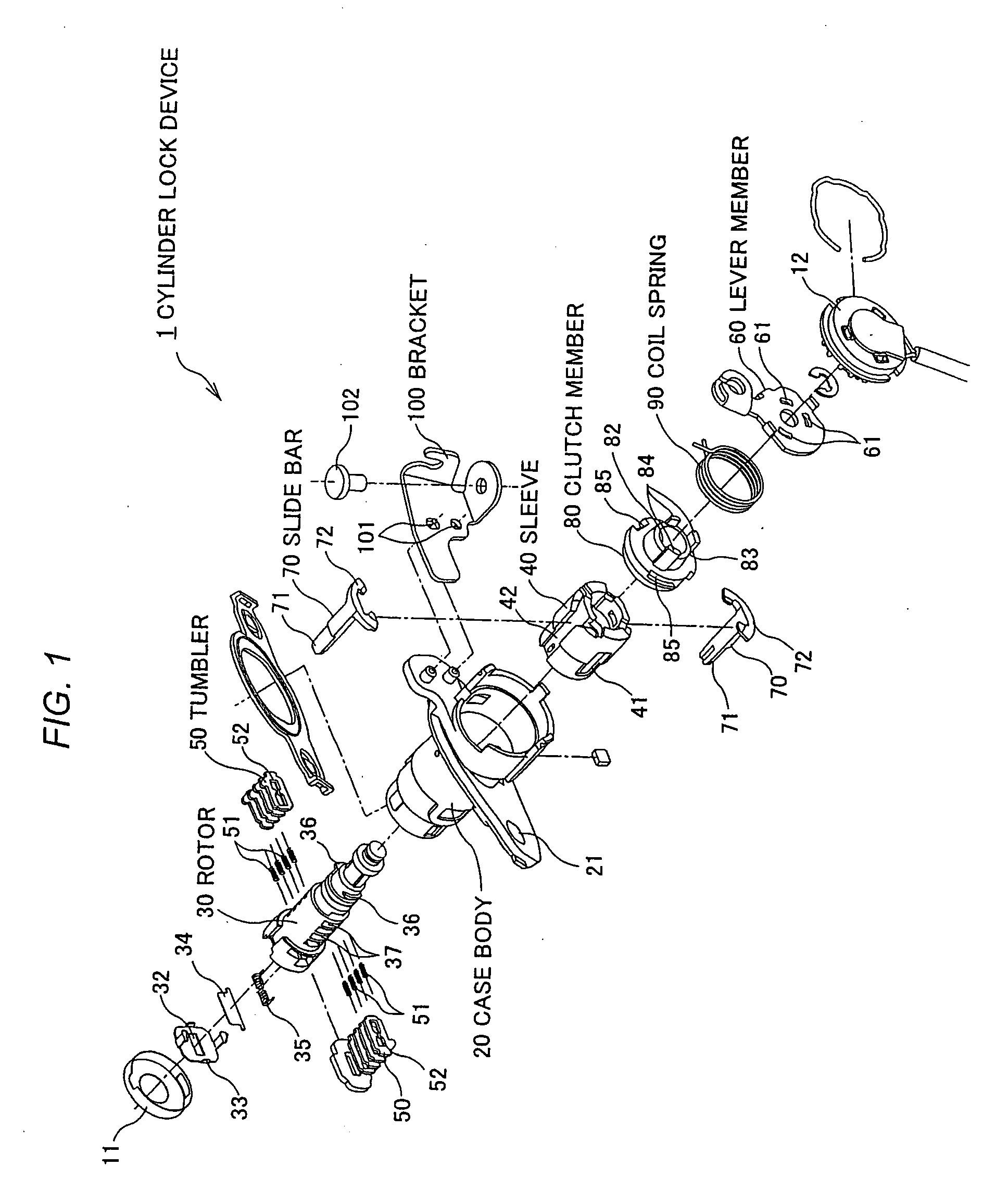
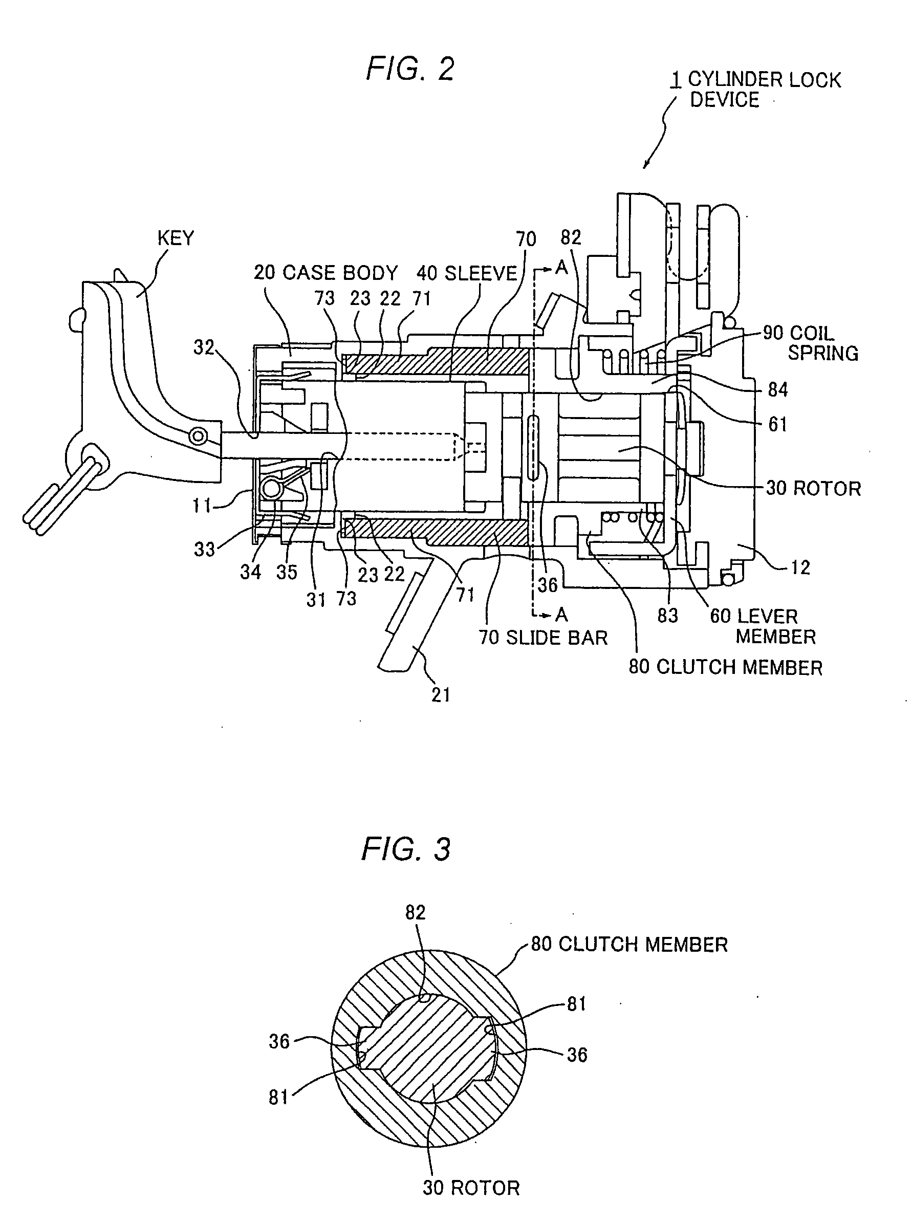
[0058] A cylinder lock device according to an embodiment of the invention will be described in detail hereinafter with reference to FIGS. 1 to 7. FIG. 1 is an exploded perspective view of a cylinder lock device according to an embodiment of the invention, FIG. 2 is a vertical cross sectional view of the cylinder lock device in an initial state according to the embodiment of the invention, FIG. 3 is a cross sectional view, showing a relationship between a rotor and a clutch member, taken on line A-A of FIG. 2, FIG. 4 is a perspective view showing an external appearance of the clutch member, FIG. 5 is a vertical cross sectional view of the cylinder lock device shown in FIG. 1 in a state in which the rotor is rotated by 180° by using an improper key, FIG. 6 is a cross sectional view, showing a relationship between the rotor and the clutch member, taken on line B-B of FIG. 5, and FIG. 7 is a vertical cross sectional view of the cylinder lock device shown in FIG. 1 in a state in which a ...


PUM


Abstract

A cylinder lock device (1) includes: a rotor (30) rotatably disposed inside a cylindrical case body (20), a key insertion hole (31) being formed in the rotor (30) to axially extend; tumblers (50) provided in the rotor (30) to be axially movable, the tumblers (50) being radially urged outward to be engaged with a sleeve (40), the engagement of the tumblers (50) with the sleeve (40) being released when a normal key is inserted into a key insertion hole (31); slide members (70) for axially moving toward a lever member (60) side whenever the sleeve (40) relatively rotates by a predetermined angle with respect to the case body (20); a clutch member (80) disposed between the rotor (30) and the lever member (60), the clutch member (80) being provided in the lever member (60) to be axially movable; and an urgement member (90) for urging the clutch member (80) to a rotor (30) side so that the clutch member (80) is engaged with the rotor (30), in which when the slide members (70) move toward the lever member (60) side, the engagement of the clutch member (80) with the rotor (30) is released.

Description

BACKGROUND OF THE INVENTION [0001] 1. Field of the Invention [0002] The invention relates to a cylinder lock device which is constructed such that when an improper key or a foreign object such as a driver is inserted into a key insertion hole, only a rotor and a sleeve are rotated with respect to a case body, and an engagement release mechanism. [0003] 2. Description of the Related Art [0004] A cylinder lock device including a rotor which is rotatably disposed inside a cylindrical case body and which has a key insertion hole formed so as to axially extend is known as one for use in a door or the like of an automobile vehicle. In the cylinder lock device, a plurality of tumblers are provided in the rotor so as to be radially movable and each of the tumblers is radially urged outward to be engaged with a sleeve. Also, when a key is inserted into the key insertion hole, each of the tumblers is moved by an urging force provided by grooves of the key. When a normal key is inserted into t...

Claims


Application Information

Patent Timeline
IPC IPC(8): E05B47/00E05B15/00E05B29/06
CPCE05B17/04E05B17/0058Y10T70/7057
Inventor SHIRAMIZU, TOSHIHARUSEKI, YOSHIYUKI
Owner KK TOKAI RIKA DENKI SEISAKUSHO
Why Eureka
Try Eureka