Power supply device and illumination device

a technology of power supply device and illumination device, which is applied in the direction of semiconductor device for light source, light and heating apparatus, electroluminescent light source, etc., can solve the problem of difficult miniaturization of power supply uni

Inactive Publication Date: 2016-03-03
PANASONIC INTELLECTUAL PROPERTY MANAGEMENT CO LTD
View PDF2 Cites 4 Cited by
  • Summary
  • Abstract
  • Description
  • Claims
  • Application Information

AI Technical Summary

Benefits of technology

[0011]The present technology has been made in view of the above-described problems, and an object of the present technology is to realize miniaturization compared with a conventional example while securing the spatial distance between a power supply input portion and a signal input portion.

Problems solved by technology

Therefore, it has been difficult to miniaturize the power supply unit, if a spatial distance regulated by law (Electrical Appliances and Materials Safety Act, in Japan) between the signal input terminal and the power input terminal is to be secured.

Method used


Image

  • Power supply device and illumination device
  • Power supply device and illumination device
  • Power supply device and illumination device

Examples


embodiment 1

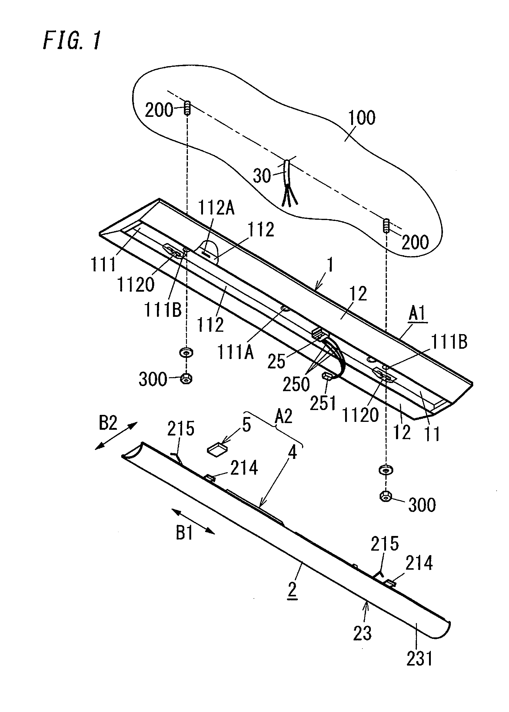
[0047]A lighting fixture A1 of the present embodiment includes a light source unit 2 and a fixture body 1, as shown in FIGS. 1 and 2. The fixture body 1 is fixed to hanging bolts 200, and is directly attached to a ceiling 100. The light source unit 2 is detachably mounted to the fixture body 1.

[0048]The fixture body 1 is formed in an elongated flat box-like shape whose upper surface (a surface opposing to the ceiling 100) is open by bending a sheet metal. Also, the fixture body 1 is provided with, on a side opposite to the ceiling 100 (lower side), a rectangular recessed portion 11 for housing the light source unit 2 over the entire length of the fixture body 1 in a longitudinal direction (front-back direction) B1. Also, inclined portions 12 are provided on two sides of the recessed portion 11 in a width direction (horizontal direction) B2 of the fixture body 1. The inclined portions 12 extend in the width direction B2 of the fixture body 1 from respective opening edges of the reces...

embodiment 2

[0118]A power supply device A2 according to Embodiment 2 will be described in detail with reference to FIGS. 20 to 22. Note that the power supply device A2 of the present embodiment is characterized by a mounting structure for mounting a second case 59 of the functional unit 5 to the first case 42 of the power supply unit 4, and the other configurations are basically in common with the power supply device A2 of Embodiment 1. Accordingly, constituent elements in common with the power supply device A2 of Embodiment 1 are provided with the same reference numerals, and illustration and description thereof will be omitted as appropriate.

[0119]The second case 59 in the present embodiment includes three coupling male portions 590, 591, and 592, as shown in FIGS. 21 and 22. The first coupling male portion 590 includes: a support piece 5900 that has a rectangular shape and projects backward from a back end of a left side wall 5960 of the second case 59; and a protruding portion 5901 shaped l...

embodiment 3

[0131]A power supply device A2 according to Embodiment 3 will be described in detail with reference to FIGS. 24 and 25. Note that the power supply device A2 of the present embodiment is characterized by a mounting structure for mounting a second case 58 of the functional unit 5 to the first case 42 of the power supply unit 4, and the other configurations are basically in common with one of the power supply devices A2 of Embodiments 1 and 2. Accordingly, constituent elements in common with one of the power supply devices A2 of Embodiments 1 and 2 are provided with the same reference numerals, and illustration and description thereof will be omitted as appropriate.

[0132]The second case 58 in the present embodiment includes a second case body 58A and a second case cover 58B, as shown in FIG. 24. The second case body 58A is constituted by a synthetic resin molded article shaped like a box in which an upper surface is open, and houses therein a second print wiring board 50A (refer to FIG...


PUM


Abstract

A power supply device includes a power supply input portion, a rectification portion, a smoothing portion, a power conversion portion, a power supply output portion, a signal input portion, a control portion, a circuit substrate, and a case. The circuit substrate is formed in an elongated rectangular plate-like shape. The power supply input portion is mounted on a first end portion of the circuit substrate in a longitudinal direction. The rectification portion, the smoothing portion, the power conversion portion, the control portion, and the power supply output portion are mounted on the circuit substrate in the stated order from the first end portion toward a second end portion in the longitudinal direction. The signal input portion is mounted at a position closer to the second end portion than the rectification portion in the circuit substrate.

Description

CROSS-REFERENCE TO RELATED APPLICATION[0001]This application claims the benefit of priority of Japanese Patent Application Number 2014-177339, filed on Nov. 1, 2014, the entire contents of which are hereby incorporated by reference.TECHNICAL FIELD[0002]This disclosure relates to power supply devices and illumination devices, and specifically relates to a power supply device that converts an AC voltage (AC current) to a DC voltage (DC current), and supplies the DC voltage (DC current) to a load, and an illumination device including the power supply device and a light source serving as the load.BACKGROUND ART[0003]A lighting fixture (illumination device) described in JP 2014-86166 A (hereinafter referred to as “Document 1”) is illustrated as a conventional example. The lighting fixture of the conventional example is a line type lighting fixture that is provided in an embedded state on a ceiling, and includes an elongated main body, a light source, and a lighting apparatus (power suppl...

Claims


Application Information

Patent Timeline
Patent Type & Authority Applications(United States)
IPC IPC(8): H02M1/00H02M1/14H02M7/06H05B44/00
CPCH02M7/06H05B33/0815H02M1/14F21V17/164F21V23/008F21Y2115/10H05B45/00H05B45/38H05B45/375
Inventor HAMAMOTO, KATSUNOBUYAMAMURA, YASUNORITAMURA, TETSUSHI
Owner PANASONIC INTELLECTUAL PROPERTY MANAGEMENT CO LTD
Why Eureka
Try Eureka