Optical transmitter-receiver module

a technology of optical transmitter and receiver module, which is applied in the direction of optical elements, semiconductor lasers, instruments, etc., can solve the problems of low production efficiency of optical transmitter-receiver modules, increased components, and failure of subscriber devices

Inactive Publication Date: 2008-08-14
NEC CORP
View PDF9 Cites 4 Cited by
  • Summary
  • Abstract
  • Description
  • Claims
  • Application Information

AI Technical Summary

Benefits of technology

[0014]According to such an optical transmitter-receiver module, the optical intensity regulating device is formed within the planar lightwave circuit. Therefore, the light output level can be varied without limitation, so the light transmission distance can be varied, without changing the mounting position of the light emitting element or modifying the light emitting element itself which is a conventional method of regulating the light output level. Further, since the size of the optical transmitter-receive module is not changed, miniaturization can be realized.
[0015]As an exemplary advantage according to the invention, since the light intensity regulating device (variable optical attenuator) is provided on the planar lightwave circuit (PLC) inside the optical transmitter-receiver module for concentric bi-directional WDM, the light output level can be varied without limitation, so the light transmission distance can be varied, without changing the mounting position of a laser oscillation element or modifying the laser oscillation element itself which is a conventional method of regulating the light output level. Further, since the light intensity regulating device (variable optical attenuator) is provided on the PLC, the size of the optical transmitter-receiver module is not changed, so miniaturization can be realized.

Problems solved by technology

For instance, in a subscriber system, when a laser oscillation element in an optical transmitter-receiver module transmits a signal light of a high level which is beyond necessity, it may affect devices in the optical transmitter-receiver module or may damage equipment of the receiving side, and what is more, the signal light may reach even an unrelated subscriber device to thereby cause the subscriber device to malfunction.
This leads to an increase in the number of components and the module type is complicated, causing a problem of low production efficiency of the optical transmitter-receiver module or a cost increase.
However, if a power regulator or an attenuator is provided in the second stage of an optical transmitter-receiver as described in Patent Document 2, it occupies a space for two devices.
Thereby, miniaturization of the optical transmitter-receiver becomes meaningless.
Further, even regulating the level of signal light in the second stage of the optical transmitter-receiver, effects on the devices in the optical transmitter-receiver will not be eliminated.

Method used


Image

  • Optical transmitter-receiver module
  • Optical transmitter-receiver module
  • Optical transmitter-receiver module

Examples


Embodiment Construction

[0021]Hereinafter, exemplary embodiments of the present invention will be described with reference to the drawings.

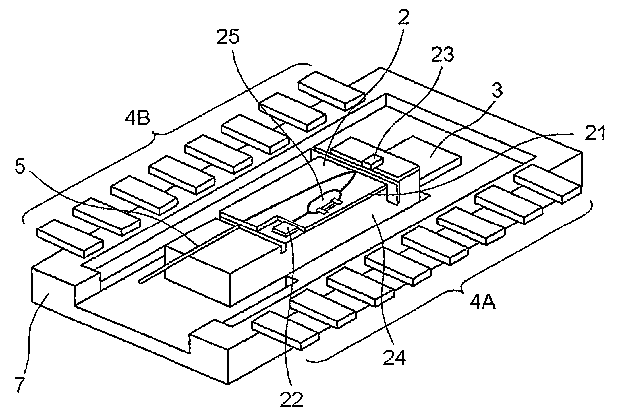
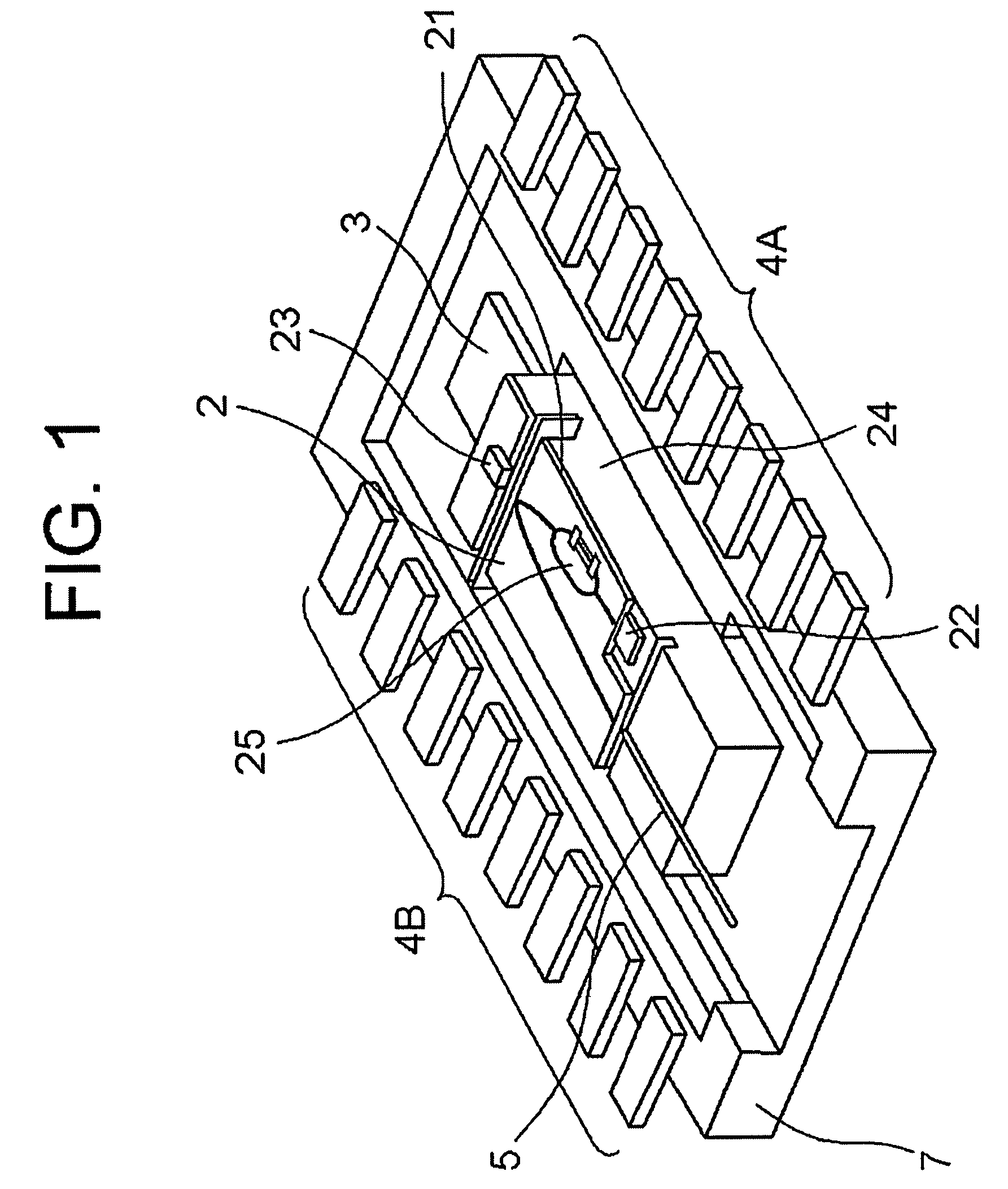
[0022]FIG. 1 shows the configuration of an optical transmitter-receiver according to a first exemplary embodiment.

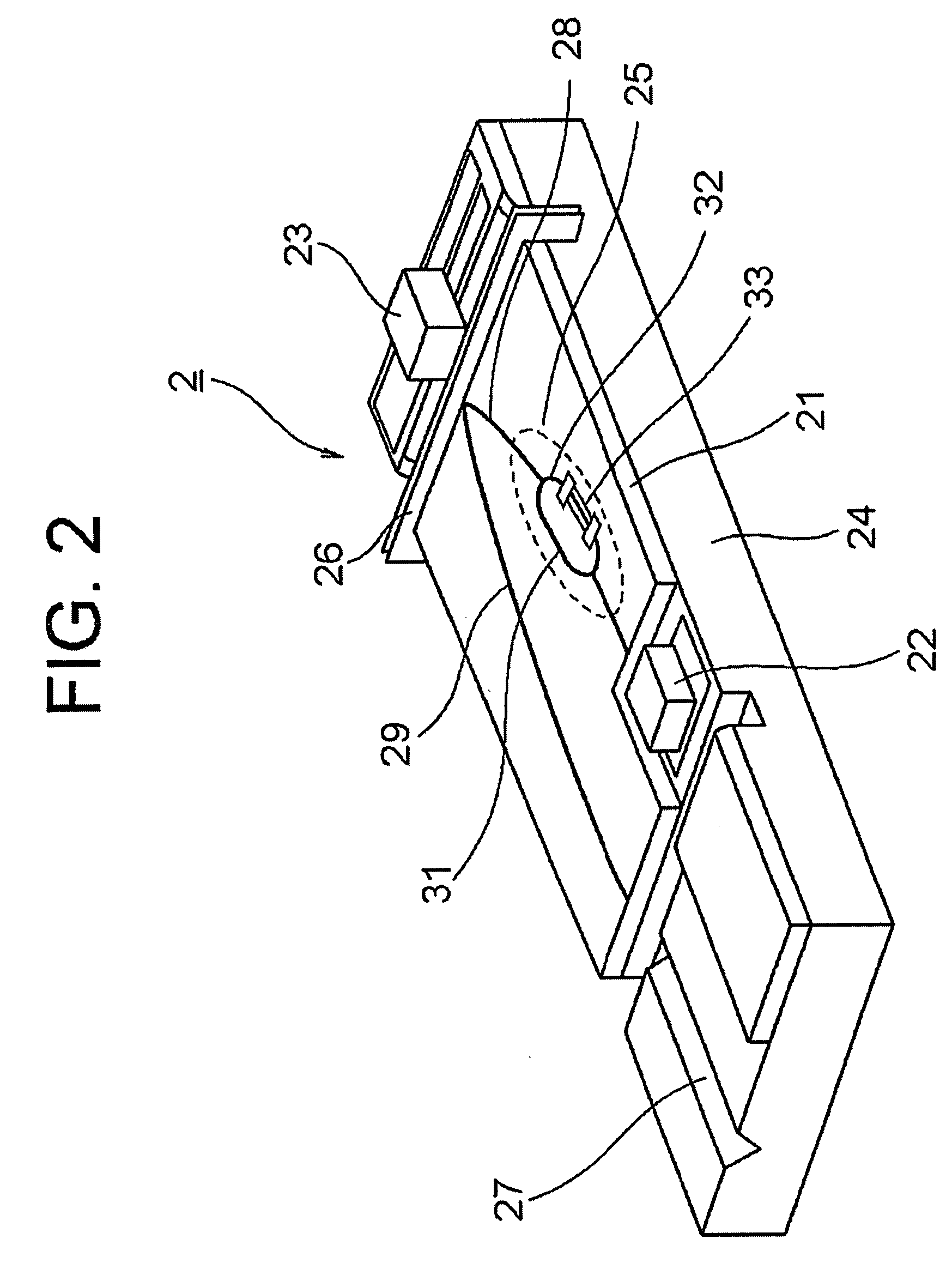
[0023]Referring to FIG. 1, the optical transmitter-receiver of the first exemplary embodiment includes an optical transmitter-receiver module 2 and a tranceimpedance amplifier IC 3, inside a ceramic package 7. The optical transmitter-receiver module 2 is configured as a hybrid integrated module in which a semiconductor laser element 22 and a photodiode element 23 are integrated on a silicon substrate 24 including a waveguide substrate 21, laminated thereon, which forms a planar lightwave circuit (unit structure). The transimpedance amplifier IC 3 converts a current output from the photodiode element 23 of the optical transmitter-receiver module 2 into a voltage. The optical transmitter-receiver module 2 is provided with an optical fiber 5.

[0024]The ceramic p...


PUM


Abstract

A small optical transmitter-receiver module capable of regulating the light output level, without changing the mounting position of a laser diode or modifying the laser diode itself, is provided. In the module, a waveguide substrate which forms a planar lightwave circuit, a semiconductor laser element serving as a laser oscillation element which oscillates laser light to be output to the outside transmission path through the planar lightwave circuit, and a photodiode element serving as a light receiving element which receives laser light from the outside transmission path through the planar lightwave circuit, are integrated on a silicon substrate. On an optical waveguide of the planar lightwave circuit, a variable optical attenuator for laser light propagating the optical waveguide is arranged.

Description

[0001]This application is based upon and claims the benefit of priority from Japanese patent application No. 2006-271016, filed on Oct. 2, 2006, the disclosure of which is incorporated herein in its entirety by reference.BACKGROUND OF THE INVENTION[0002]1. Field of the Invention[0003]The present invention relates to an optical transmitter-receiver module used for optical fiber communications, and in particular, relates to an optical transmitter-receiver module for concentric bi-directional WDM (Wavelength Division Multiplexing).[0004]2. Related Art[0005]As accesses to information such as moving images over the Internet increase in recent years, expansion of the capacity to transmit information is widely demanded even by general users. Along with the demands, the range of applying optical communications expands rapidly not only to backbone systems but also to subscriber systems.[0006]In a bi-directional communication system in which optical signals of different wavelength are transmi...

Claims


Application Information

Patent Timeline
Patent Type & Authority Applications(United States)
IPC IPC(8): H04B10/00G02B6/122G02B6/30G02B6/42H01S5/022
CPCH04B10/40
Inventor SHINODA, TAKUYA
Owner NEC CORP
Why Eureka
Try Eureka