Screw type three-phase medium separator

A spiral and separator technology, which is applied in the field of multiphase medium separation and treatment devices, can solve problems such as oilfield production hazards, pressure instability, clogging, etc., achieve broad engineering application prospects, reduce radial dimensions, and improve separation efficiency Effect

Active Publication Date: 2015-03-25
NORTHEAST GASOLINEEUM UNIV
View PDF3 Cites 23 Cited by
  • Summary
  • Abstract
  • Description
  • Claims
  • Application Information

AI Technical Summary

Problems solved by technology

Absorption is often used in the treatment and recovery of gaseous pollutants; the adsorption of activated carbon depends on its solubility, surface free energy, polarity, size and unsaturation of adsorbate molecules, concentration of adjuncts, etc.; membrane separation is driven by pressure. Separation is carried out by means of the adsorption capacity of each component in the gas on the surface of the polymer membrane and the difference in dissolution-diffusion in the membrane, that is, the difference in permeation rate, the equipment cost is high, and the requirements for the medium condition are relatively strict.
At present, the produced fluids of most oilfields in my country contain a large amount of impurities such as associated gas and mud and sand. These impurities will not only cause pressure instability and increase the difficulty of transportation, but also cause corrosion and blockage of equipment, and there are many potential safety hazards. Oil field production poses great harm

Method used


Image

  • Screw type three-phase medium separator
  • Screw type three-phase medium separator
  • Screw type three-phase medium separator

Examples


Embodiment approach

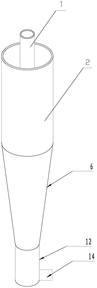
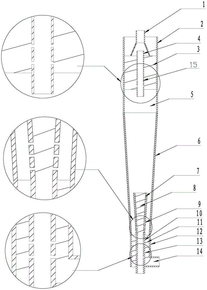
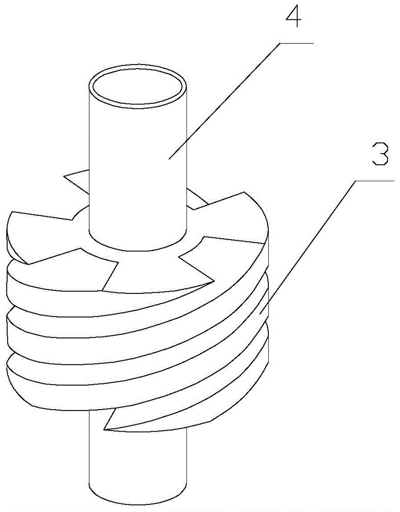
[0027] If the diameter of the first straight pipe section 2 is set as D, the diameter of the overflow pipe 4 is D 1 , The diameter of the discharge pipe 10 is D 2 , the height of the swirl chamber 5 is H, and the height of the first spiral channel is H 1 , the length of the overflow pipe 4 extending into the swirl chamber is L, and the height of the second straight pipe section 12 is H 2 , the cone angle of the outer cone section 6 is α, and the height of the part located in the separator after the outer cone section 6 is connected with the discharge pipe 10 is H 3 , The diameter of the second straight pipe section 12 is D 3 , then constructing the separator according to the limited range of the following formula (1) to formula (9) will achieve the best effect.

[0028] 0.1D1 <0.5D...Formula (1);

[0029] 0.2D2 <0.7D...Formula (2);

[0030] 2D

[0031] 2D1 <4D...Formula (4);

[0032] 0.05H< L<0.5H...Formula (5);

[0033] 0.5H2 <1.2H...Formula (6)...


PUM

PropertyMeasurementUnit
pore sizeaaaaaaaaaa
pore sizeaaaaaaaaaa
pore sizeaaaaaaaaaa

Abstract

The invention discloses a screw type three-phase medium separator, and mainly aims at providing equipment capable of synchronously carrying out degassing and desanding treatment on produced liquid for oilfield production. The weight of separation equipment is reduced; and the economic benefits of oilfield exploitation are improved. The screw type three-phase medium separator is characterized in that a first screw runner is fixed in a first straight pipe section and runs through an overflow pipe; a plurality of first micro-pores are formed in the 1 / 3 part below the overflow pipe; a flow guide body is arranged in the first straight pipe; a horn opening of the flow guide body is inversely fixed in the center of the first spiral runner; an air outlet pipe and the overflow pipe have the same center axes; a second spiral runner and a drain pipe are arranged in a second straight pipe section; a plurality of second micro-pores which run through the pipe body are formed in the middle section of the drain pipe; a filter cone is arranged in an outer cone section; a third spiral runner is arranged in the filter cone; a plurality of third micro-pores are formed in the 1 / 3 part below the filter cone, and are vertical to the wall surface of the filter cone; and the bottom end of the filter cone is connected with the head end of the drain pipe.

Description

technical field [0001] The invention relates to a multi-phase medium separation and treatment device applied in the fields of petroleum, chemical industry, marine engineering, water treatment and environmental protection. Background technique [0002] With the continuous deepening of the development of many oilfields in my country, the sand content of the produced fluid and the amount of associated gas are increasing year by year. A large amount of sand and gas in the produced fluid will cause great damage to the ground gathering and transportation equipment, and degassing and desanding are indispensable. At present, the sand removal equipment used in oil fields mainly includes gravity sedimentation, filter sand removal, centrifugal sand removal and cyclone sand removal. Among them, gravity settling (tank) belongs to the gravity separation method, which uses density difference for separation. The disadvantage is that it occupies a large area, which is suitable for the lan...

Claims


Application Information

Patent Timeline
Patent Type & Authority Applications(China)
IPC IPC(8): C02F9/02C02F103/10
CPCC02F1/20C02F1/38C02F2103/10
Inventor 蒋明虎赵立新李永山李枫张勇徐保蕊
Owner NORTHEAST GASOLINEEUM UNIV
Why Eureka
Try Eureka