

Impact Resistant Fishing Rod Case
Patent Information
- Authority / Receiving Office
- US · United States
- Current Assignee / Owner
- PIERSON EDWARD
- Publication Date
- 2020-05-21
- Estimated Expiration
- Not applicable · inactive patent
Smart Images
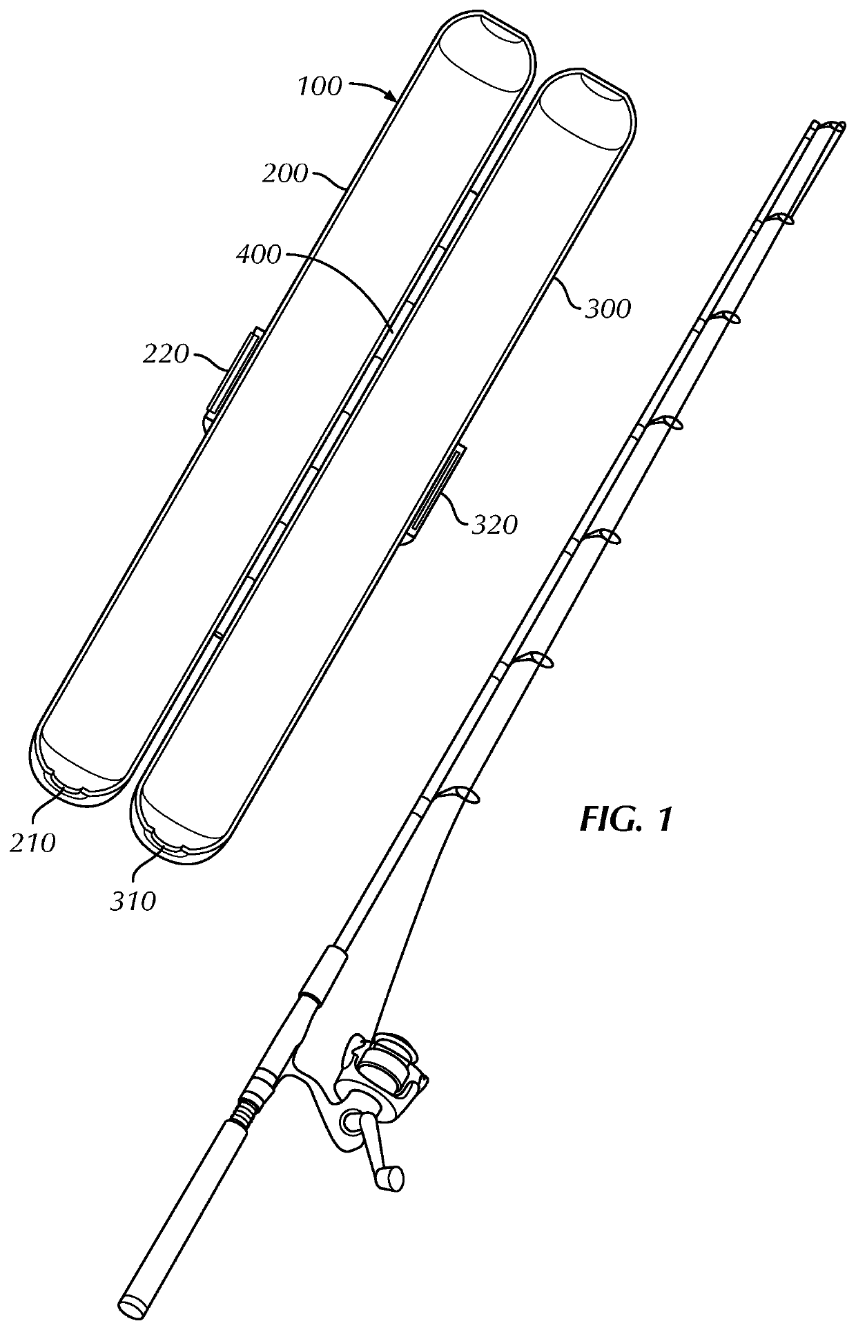
Figure 1 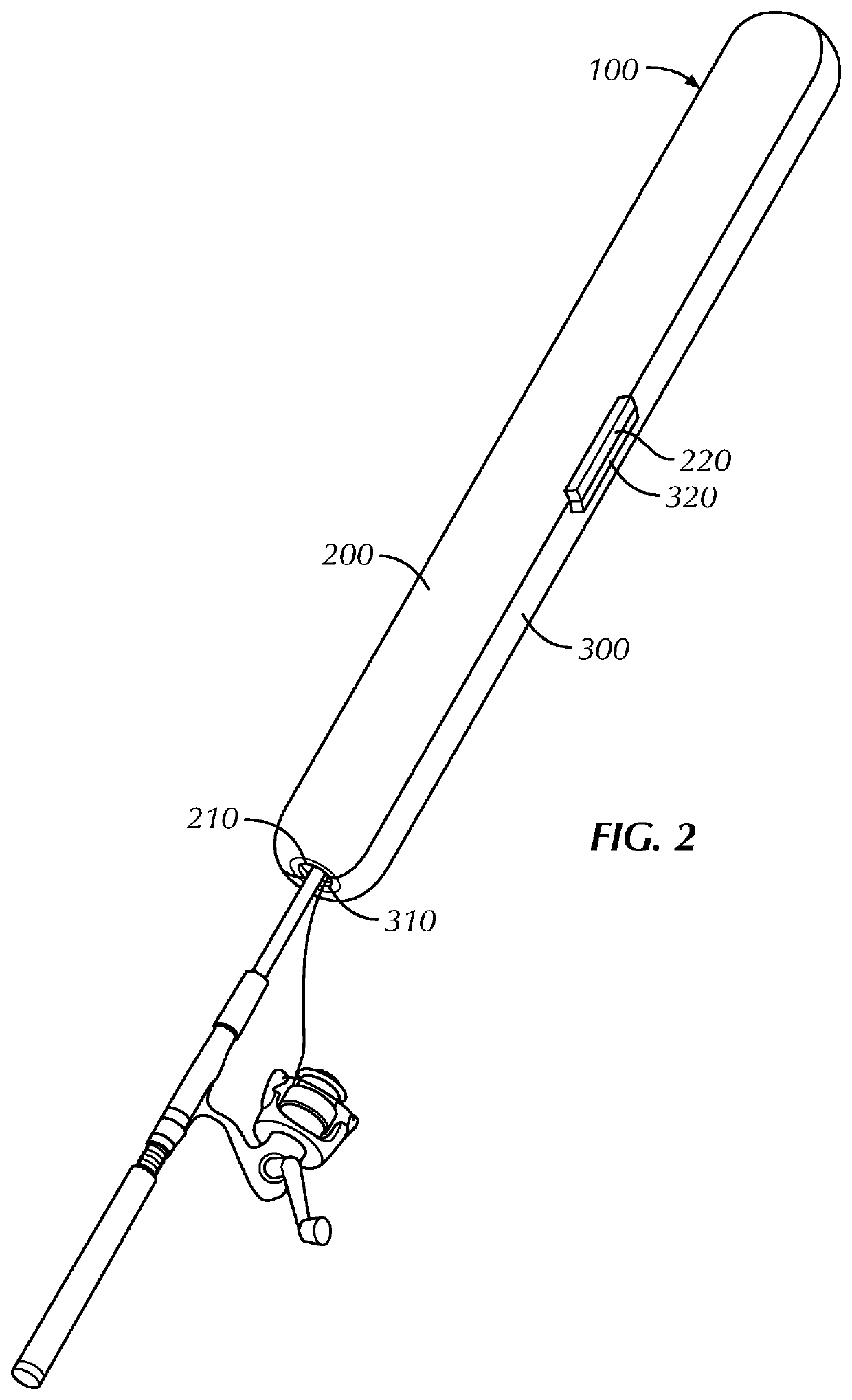
Figure 2 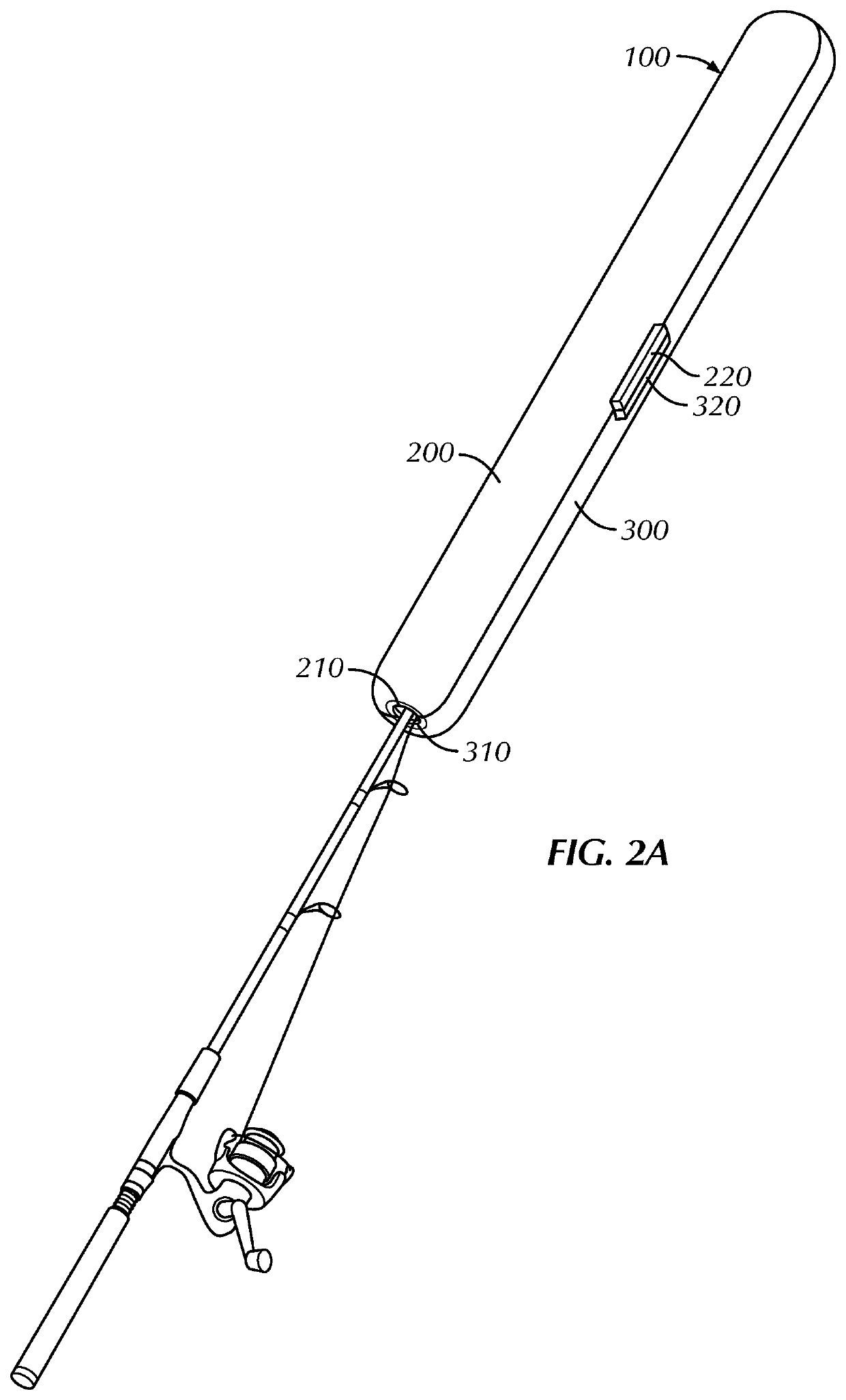
Figure 3
Abstract
Description
BACKGROUND OF THE INVENTIONField of the Invention
[0001] This invention relates to a cover for a fishing rod, and more particularly to a hinged cover that encloses the end of a fishing rod.Background of the Invention
[0002] When carrying a fishing rod, the hook is typically stored hooked into one of the eyelets of the fishing rod to prevent it from swinging freely and becoming tangled with the fishing line or snagging on nearby objects such as trees, clothing, or other fishing rods. However, the fishing hook can easily dislodged from the eyelet by movement or if the release button In addition, it is also necessary to ensure that impacts do not damage the rod or cause it to snap during transport. As the rod narrows towards the tip, it becomes more vulnerable to breakage with the tip of the rod being the easiest portion to snap off and the wider base being the hardest. For example, when the rod is stored in a car trunk or boat storage compartment for a fishing trip heavy objects such as b...