
Flow divider and ecology valve

a flow divider and ecology valve technology, applied in the direction of turbine/propulsion fuel valves, mechanical equipment, machines/engines, etc., can solve the problems of complex high cost and weight ecology systems, affecting the performance of the nozzle, etc., and achieve the effect of conserving size, weight and complexity

Inactive Publication Date: 2006-08-22
HONEYWELL INT INC
View PDF18 Cites 19 Cited by
  • Summary
  • Abstract
  • Description
  • Claims
  • Application Information

AI Technical Summary

Benefits of technology

The present invention provides a solution for selectively conveying fuel from a fuel source to a primary and secondary gas turbine engine intake manifold during engine operation and withdrawing fuel therefrom upon cessation of engine operation. The invention includes a flow dividing valve and an ecology valve (piston reservoir) assembly packaged on a common centerline, in a common body. The flow dividing valve has an inlet and two outlets, one of which is dedicated to the primary engine and the other dedicated to the secondary engine. The ecology valve is controlled solely by the fuel pressure differential between the inlet and the outlet for withdrawing fuel from the secondary engine intake manifold when the engine is de-energized thereby purging the manifold of fuel, and returning withdrawn fuel to the manifold during subsequent engine operation. The invention has the advantage of conserving size, weight, and complexity.

Problems solved by technology

Fuel removal is required to keep fuel from vaporizing into the atmosphere and to avoid fuel coking on the engine's fuel nozzles, a condition that hinders nozzle performance.
These types of architecture result in complex high cost and weight ecology systems.

Method used


Image

  • Flow divider and ecology valve
  • Flow divider and ecology valve
  • Flow divider and ecology valve

Examples


Embodiment Construction

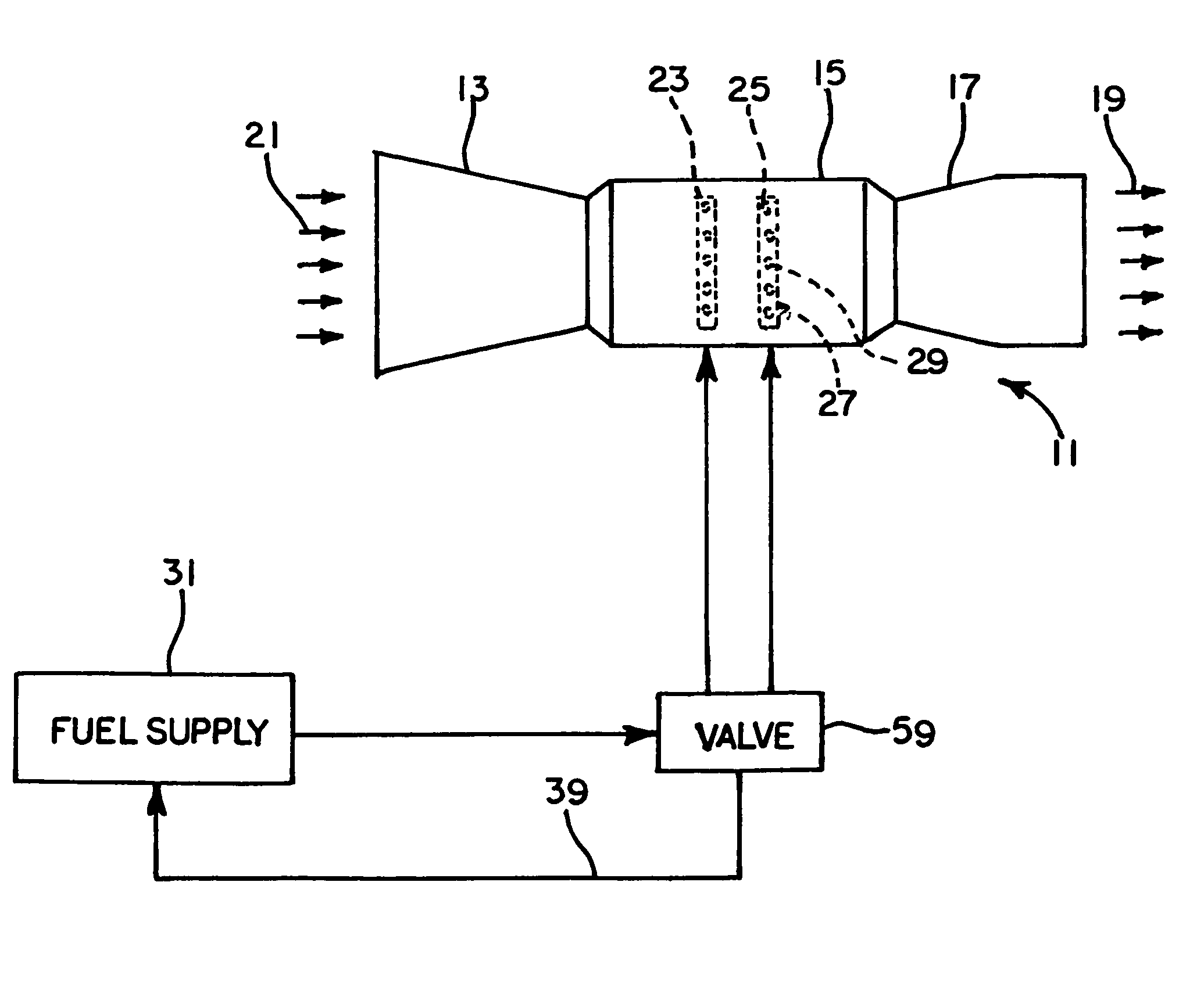
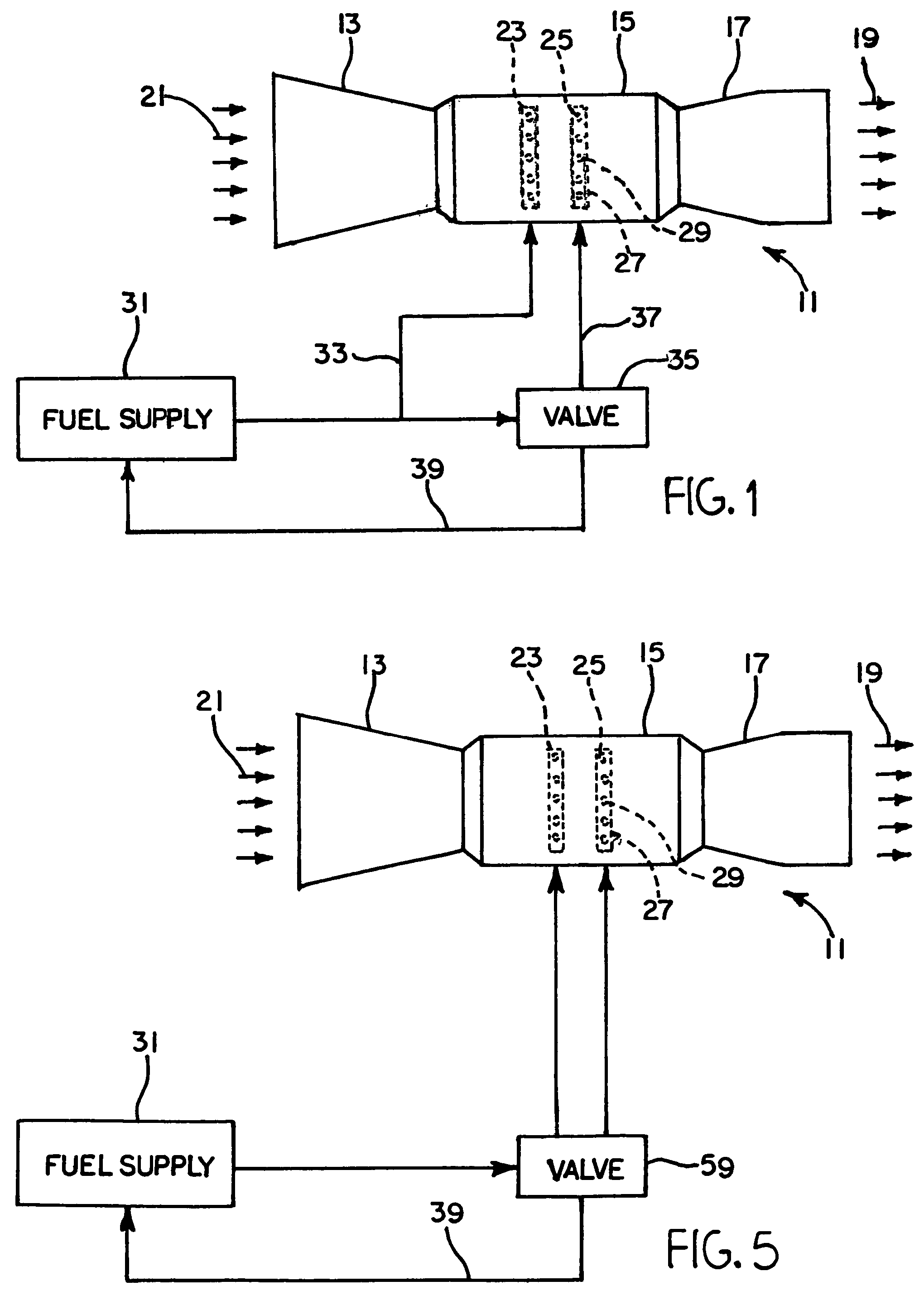
[0019]Referring now to the drawings and particularly to FIG. 1, there is shown a fuel supply system for a gas turbine engine 11 having, for example, an air inlet compressing section 13, a combustion region 15 and a turbine section 17. Combustion products exiting the engine are illustrated at 19 and incoming air is shown at 21. Combustion region 15 may include fuel intake manifolds such as a primary manifold 23 and a secondary manifold 25 with nozzles such as 27 and 29 for introducing fuel into the combustion region. The manifolds may, for example, be generally annular hollow structures with the nozzles distributed about the inner annular surfaces. Fuel is supplied to the manifolds from a fuel source 31 which may include conventional pump, metering valve, pressurizing valve, bypass valves and flow meter as desired. Fuel flow from source 31 to the primary manifold 23 is directly by way of line 33 while fuel flows through a valve 35 on its way to secondary manifold 25. A low pressure f...


PUM


Abstract

A fuel flow dividing ecology valve conveys fuel from a fuel source to at least a secondary gas turbine engine intake manifold during engine operation and withdraws fuel therefrom upon cessation of engine operation. The valve includes a flow dividing valve portion having an inlet coupled to the fuel source and an outlet coupled to the secondary manifold. The valve also includes an ecology valve portion controlled by the fuel pressure differential between the fuel source and the flow restricting inlet. The ecology valve portion includes a housing with a movable piston disposed therein. The piston defines, in conjunction with the housing, a variable volume chamber for withdrawing fuel from the engine intake manifolds. When the engine is de-energized, the piston moves from a first position toward a second position thereby purging the manifolds of fuel.

Description

[0001]This application is a divisional of co-pending U.S. application Ser. No. 10 / 179,783 filed Jun. 25, 2002 the entire contents of which are herein incorporated by reference.BACKGROUND OF THE INVENTION[0002]1. Field of the Invention[0003]The present invention relates to fuel supply systems and more particularly to a flow divider and ecology valve for supplying fuel to an engine manifold and withdrawing fuel therefrom upon engine shut-down.[0004]2. Description of the Related Art[0005]Gas turbine engine fuel delivery systems may require multiple fuel manifolds and an arrangement for apportioning fuel flow among those manifolds to segregate various types of fuel nozzles for optimal engine performance. For example, U.S. Pat. No. 5,809,771 to Wernberg discloses a fuel flow splitting valve having a single piston operable in two different regions, one for modulating flow to primary and secondary engine nozzles as a function of fuel pressure and another where flow to primary and secondary...

Claims


Application Information

Patent Timeline
Patent Type & Authority Patents(United States)
IPC IPC(8): F02C7/228F02C7/22F02C7/232F02C9/26
CPCF02C7/228F02C9/26F02C7/232
Inventor FUTA, JR., PAUL W.DEMERS, DENNIS G.
Owner HONEYWELL INT INC
Features
  • Generate Ideas
  • Intellectual Property
  • Life Sciences
  • Materials
  • Tech Scout
  • Unparalleled Data Quality
  • Higher Quality Content
  • 60% Fewer Hallucinations
Learn More