
Rotor for a vane pump, made of plastic material reinforced by metallic foil

a technology of plastic material and rotor, which is applied in the direction of rotary/oscillating piston pump components, machines/engines, liquid fuel engines, etc., can solve the problems of unavoidable material stress limitation, plastic material has not a high mechanical resistance, and the rotor of plastic material has some disadvantages, so as to improve the rotor of plastic material, avoid or reduce the disadvantages, and improve the effect of rotors made of plastic material

Inactive Publication Date: 2012-08-21
VHIT SPA
View PDF10 Cites 3 Cited by
  • Summary
  • Abstract
  • Description
  • Claims
  • Application Information

AI Technical Summary

Benefits of technology

[0010]This invention aims to improve the plastic material rotors for vane pumps, by avoiding or reducing the stated disadvantages, and thus allowing the rotors to give better performances without increasing their size and mass.
[0011]Therefore, the subject of this invention is a rotor, moulded of plastic material, intended to be rotatably mounted into a cavity of a pump body, and having a space intended to accommodate one or more vanes forming the pumping members, characterized in that at least a part of the surfaces thereof, intended to undergo sliding displacements against other pump members, is covered by at least one metallic foil caused to adhere to the subjacent surface of plastic material, intended to reduce the resistances to the sliding displacements and also to mechanically reinforce the rotor. Said metallic foil can preferably consist of a steel sheet or an aluminum alloy sheet.
[0012]The application of the feature according to the invention allows attaining various considerable advantages. In particular, the mechanical resistance of the rotor is increased without having recourse to increased cross sections and therefore to an increased mass of plastic material. It is therefore possible to provide rotors having performances like those of the usual rotors, by somewhat reducing the size, the weight and finally the cost thereof, or even to conserve the size of a rotor by increasing its performances without increasing its mass and cost. For example, it becomes possible to have the pump rotating at an increased speed and therefore giving higher performances. For example, on a diesel engine it becomes possible to have the pump driven by an output shaft more rapid than that usually employed. Such pumps may also find useful applications on gasoline engines, wherein the rotational speed is larger that that of diesel engines. In designing the pump it is possible to provide a larger axial extension of the vanes, thus attaining a larger volume with a same rotor diameter. Also, a better resistance to the temperature is attained, whereby work conditions are allowed, that are more burdensome than those usually allowable.

Problems solved by technology

However, the rotors of plastic material have some disadvantages.
The plastic material has not a high mechanical resistance, it is relatively subject to wear in the portions subject to gliding contact, it is subject to non negligible ageing phenomena, and it is considerably sensible to the changes in temperature, which are particularly severe in the applications to motor vehicles, where the pump is required to operate within a large temperature field from −40° C. to +150° C.
According to the known technique, these disadvantages may be partially overcome or reduced by having recourse to special complicated rotor shapes and to an increase of the cross sections thereof and therefore of the quantity of material used, and in any event it is unavoidable to accept a suitable limitation of the stresses undergone by the material, to which correspond some limitations of the possible rotor performances.

Method used


Image

  • Rotor for a vane pump, made of plastic material reinforced by metallic foil
  • Rotor for a vane pump, made of plastic material reinforced by metallic foil
  • Rotor for a vane pump, made of plastic material reinforced by metallic foil

Examples


Embodiment Construction

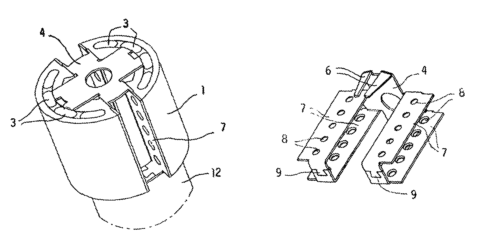
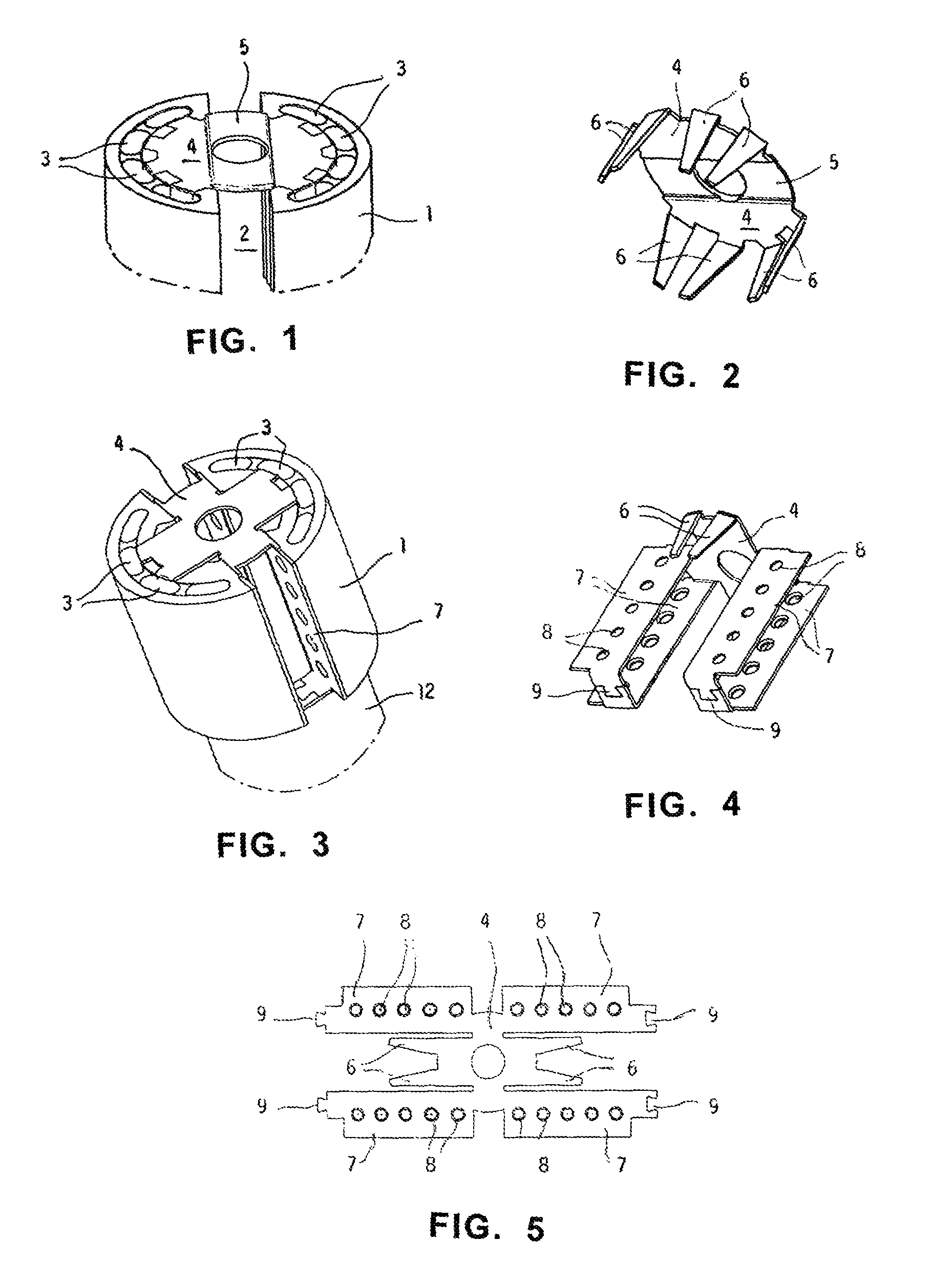
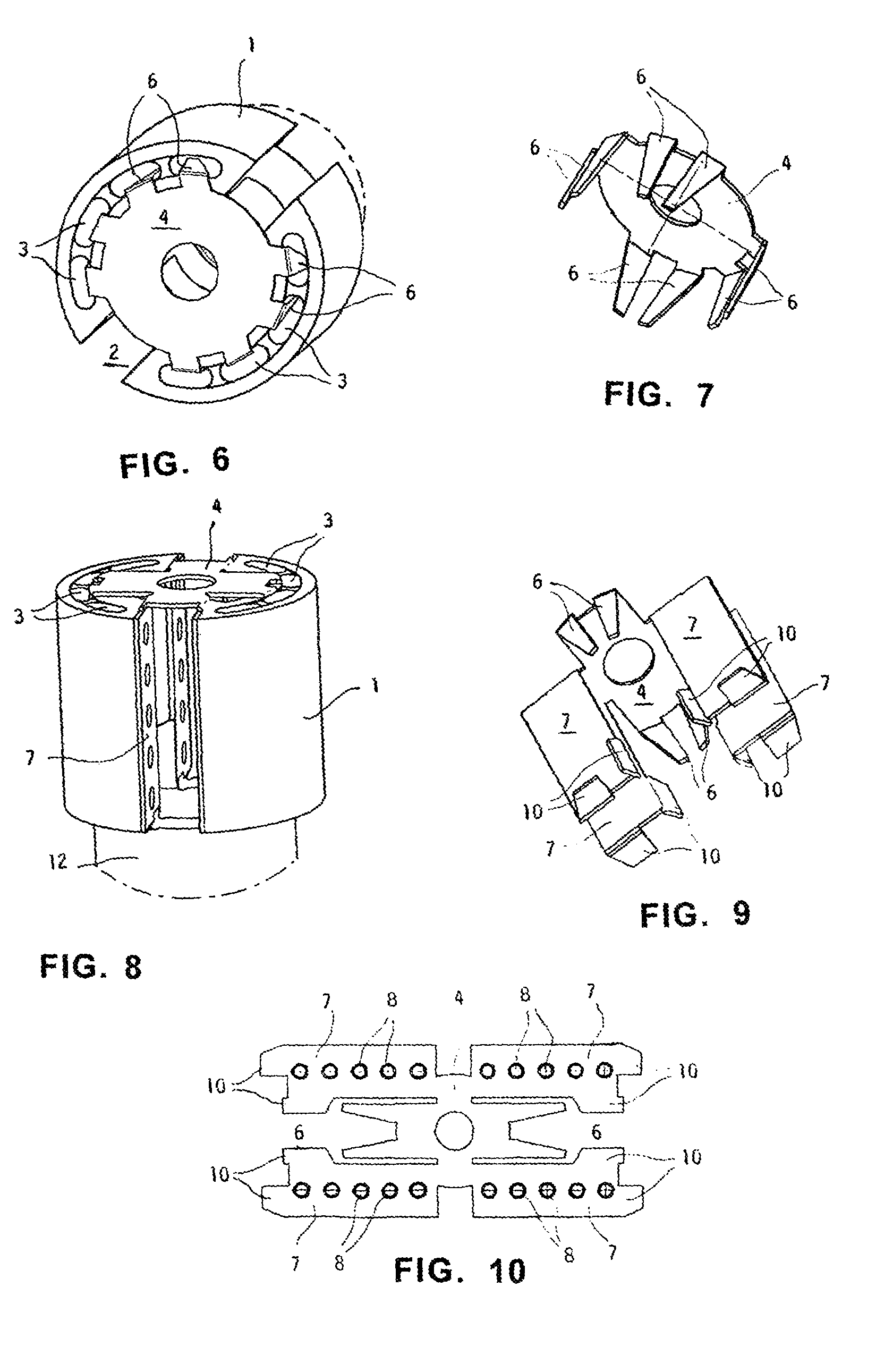
[0029]Referring now to FIG. 1, number 1 designates a first end portion of a rotor for a vane pump, which is embodied of plastic material, and number 12 designates a second end portion coupled to the first end portions 1 of the rotor. This end portion is pivoted to the pump body and it is intended to rotate contacting a wall of the cavity of the pump body (not represented). Rotor 1 is provided with a space 2 intended to receive and guide one or two vanes (not represented). Moreover rotor 1 has several cavities 3 whose aim is to reduce the weight of the rotor body as well as the quantity of material needed for its manufacture. According to the invention, in order to reinforce this end portion of rotor 1, use is made of a metallic foil (made for example of steel sheet or of a suitable aluminum alloy sheet) which is shaped as shown by FIG. 2. The metallic foil has an annular plane surface 4 with a diametral portion 5 slightly projecting in correspondence with the space 2 for the vanes, ...


PUM

PropertyMeasurementUnit
temperatureaaaaaaaaaa
resistancesaaaaaaaaaa

Abstract

A rotor (1-3) molded of plastic material, intended for rotary installation in a cavity of a pump body and for reception of one or more vanes forming the pumping members, characterized in that at least a part of the surfaces thereof, intended to undergo sliding displacements against other pump members, is covered by at least one metallic foil (4) caused to adhere to the subjacent surface of plastic material. The metallic foil can consist of a steel sheet or an aluminum alloy sheet, intended for reducing the resistances to the sliding as well as for mechanically reinforcing the rotor. The metallic foil can be fastened to the plastic material body (1) of the rotor by a co-molding operation, or it can be mechanically fixed to the body (1) of the rotor molded of plastic material.

Description

BACKGROUND OF THE INVENTION[0001]1. Field of the Invention[0002]The subject of the present invention is a rotor moulded of plastic material, intended for rotary installation in a cavity of a pump body and for reception of one or more vanes forming the pumping members. The vane pumps are widely used for pumping fluids, and for example they find particular applications in motor vehicles.[0003]2. Related Art[0004]To the rotor of a vane pump three operations are mainly required:[0005](1) Transmission of the motion. The rotor, which is driven in rotation within a chamber of the pump body, transmits the movement to the vane or the vanes of the pump. It undergoes sliding displacements against the surfaces of the pump body with respect to which it is made to rotate. The rotor is required not to undergo excessive wear and not to produce excessive friction during its sliding displacements.[0006](2) Guide for the vane or the vanes of the pump. The rotor guides the vane or the vanes which, duri...

Claims


Application Information

Patent Timeline
Patent Type & Authority Patents(United States)
IPC IPC(8): F01C21/08F04C29/00
CPCF01C21/0809F04C18/3441F04C2240/802F05C2225/00
Inventor CADEDDU, LEONARDOFERMINI, FRANCOPOLLONI, VITTORIO
Owner VHIT SPA
Features
  • Generate Ideas
  • Intellectual Property
  • Life Sciences
  • Materials
  • Tech Scout
  • Unparalleled Data Quality
  • Higher Quality Content
  • 60% Fewer Hallucinations
Learn More