Method for detecting magnetic field location in electric motor

a magnetic field and electric motor technology, applied in the direction of magnetic circuit rotating parts, electronic commutation motor control, magnetic circuit shape/form/construction, etc., can solve the problems of electric noise, low durability, brush nois

Active Publication Date: 2021-04-29
SHINANO KENSHI
View PDF0 Cites 0 Cited by
  • Summary
  • Abstract
  • Description
  • Claims
  • Application Information

AI Technical Summary

Benefits of technology

[0031]By employing the method of the present invention, generating noises, which is generated when detecting the magnetic field location of the electric motor, can be restrained, so the quiet method for detecting a magnetic field location in an electric motor can be realized.

Problems solved by technology

Conventionally, DC motors having brushes have been used as small DC motors, but they have problems of brush noise, electric noise, low durability, etc., so brushless DC motors have been developed to solve the problems.
In the sensorless driving manner, locations of the rotor are detected from the induced voltages, but the rotor cannot be initiated when a speed is zero because no voltages are induced in a stationary state and the location of the rotor cannot be detected.
Further, a differential amplifier, etc. are required for precise measurement, so a detection circuit must be complex.
Therefore, a production cost of an apparatus for performing this manner must be high.
Further, there are problems of a large sensing current, a long location sensing time, e.g., several dozen msec, etc.

Method used


Image

  • Method for detecting magnetic field location in electric motor
  • Method for detecting magnetic field location in electric motor
  • Method for detecting magnetic field location in electric motor

Examples


Embodiment Construction

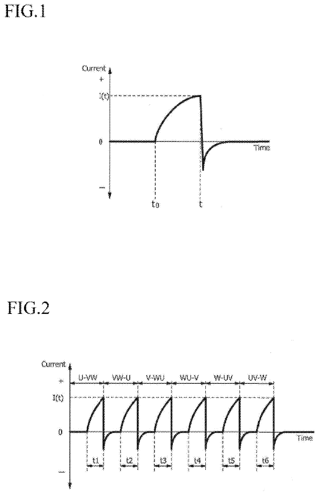
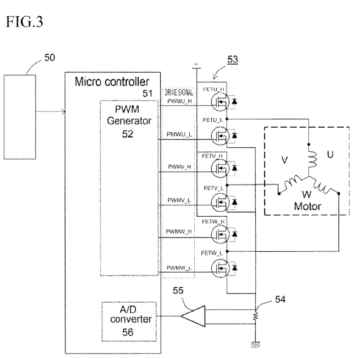
[0047]Embodiments of the method for detecting magnetic field locations of an electric motor relating to the present invention will now be described with reference to the attached drawings. In the following descriptions, a sensorless motor comprising: a rotor having a permanent magnetic field; and a stator having star-connected coils, which are arranged with a phase difference of 120° and in which phase ends are connected to a motor driving circuit, will be explained as an example of the electric motor relating to the present invention. Note that, the method of the present invention can be applied to a linear actuator, in which a movable member is reciprocally moved by an electric motor.

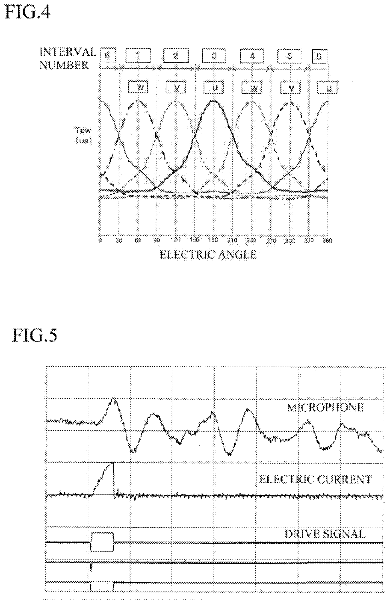
[0048]In the following descriptions, an example of a method for detecting permanent magnetic field location in a sensorless motor, e.g., three-phase brushless motor, will be explained with reference to a structure of a sensorless motor driving unit.

[0049]An example of the three-phase brushless DC moto...


PUM


Abstract

An MPU sequentially selects one from six energization patterns, applies constant voltage rectangular pulses to the three-phase coils for a prescribed sensing energization time, turns on at least the low-side arm of the three-phase half-bridge type inverter circuit so as to reflux an induced current between a switching element and the coils and attenuate the same, measures peak coil current values immediate before completing the sensing energization by an A/D-converter circuit, and stores the peak coil current values as measured data.

Description

CROSS-REFERENCE TO RELATED APPLICATION[0001]This application is based upon and claims the benefit of priority of prior Japanese Patent Application No. 2019-195906, filed on Oct. 29, 2019, and the entire contents of which are incorporated herein by reference.TECHNICAL FIELD[0002]The present invention relates to a method for detecting a magnetic field location in an electric motor, e.g., sensorless motor, linear actuator.BACKGROUND ART[0003]Conventionally, DC motors having brushes have been used as small DC motors, but they have problems of brush noise, electric noise, low durability, etc., so brushless DC motors have been developed to solve the problems. These days, sensorless motors, which have no location sensors, draw attention as compact, light, tough and low-cost motors, and they were firstly employed in information technology devices, e.g., hard disk drive unit, and then employed in home electric appliances, car-mounted devices, etc. due to progression of vector control technol...

Claims


Application Information

Patent Timeline
Patent Type & Authority Applications(United States)
IPC IPC(8): H02P6/182H02P27/08H02P23/14G01R19/04H02K1/27
CPCH02P6/182H02P27/08H02K1/27G01R19/04H02P23/14G01B7/003H02P27/085H02K11/27H02P6/186H02P2203/03
Inventor SUZUKI, KAZUKI
Owner SHINANO KENSHI
Why Eureka
Try Eureka