
Thermal system control for a vehicle
a technology for thermal management systems and motor vehicles, applied in vehicle heating/cooling devices, battery/fuel cell control arrangements, transportation and packaging, etc., can solve the problems of excessive thermal energy generation, and inability to effectively or efficiently contain motor vehicles, etc., to reduce complexity, reduce cost, and reduce mass
- Summary
- Abstract
- Description
- Claims
- Application Information
AI Technical Summary
Benefits of technology
Problems solved by technology
Method used
Image

Examples
Embodiment Construction
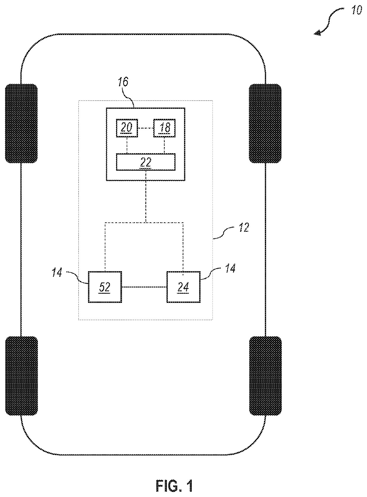
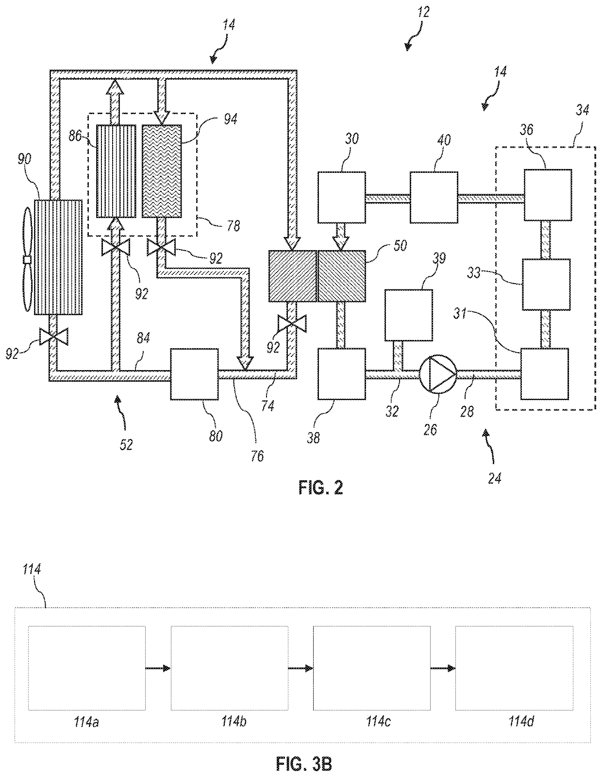
[0017]Embodiments of the present disclosure are described herein. It is to be understood, however, that the disclosed embodiments are merely examples and other embodiments can take various and alternative forms. The figures are not necessarily to scale; some features could be exaggerated or minimized to show details of particular components. Therefore, specific structural and functional details disclosed herein are not to be interpreted as limiting, but are merely representative. The various features illustrated and described with reference to any one of the figures can be combined with features illustrated in one or more other figures to produce embodiments that are not explicitly illustrated or described. The combinations of features illustrated provide representative embodiments for typical applications. Various combinations and modifications of the features consistent with the teachings of this disclosure, however, could be desired for particular applications or implementations....
PUM
 Abstract
Description
Claims
Application Information