

LCD device and OLED display device
a display device and liquid crystal display technology, applied in the field of displays, can solve the problems of severe signal noise, adversely affecting the acquisition of fingerprint recognition sensor signals, and no liquid crystal display (lcd)-based under-screen fingerprint recognition products
- Summary
- Abstract
- Description
- Claims
- Application Information
AI Technical Summary
Benefits of technology
Problems solved by technology
Method used
Image

Examples
embodiment 1
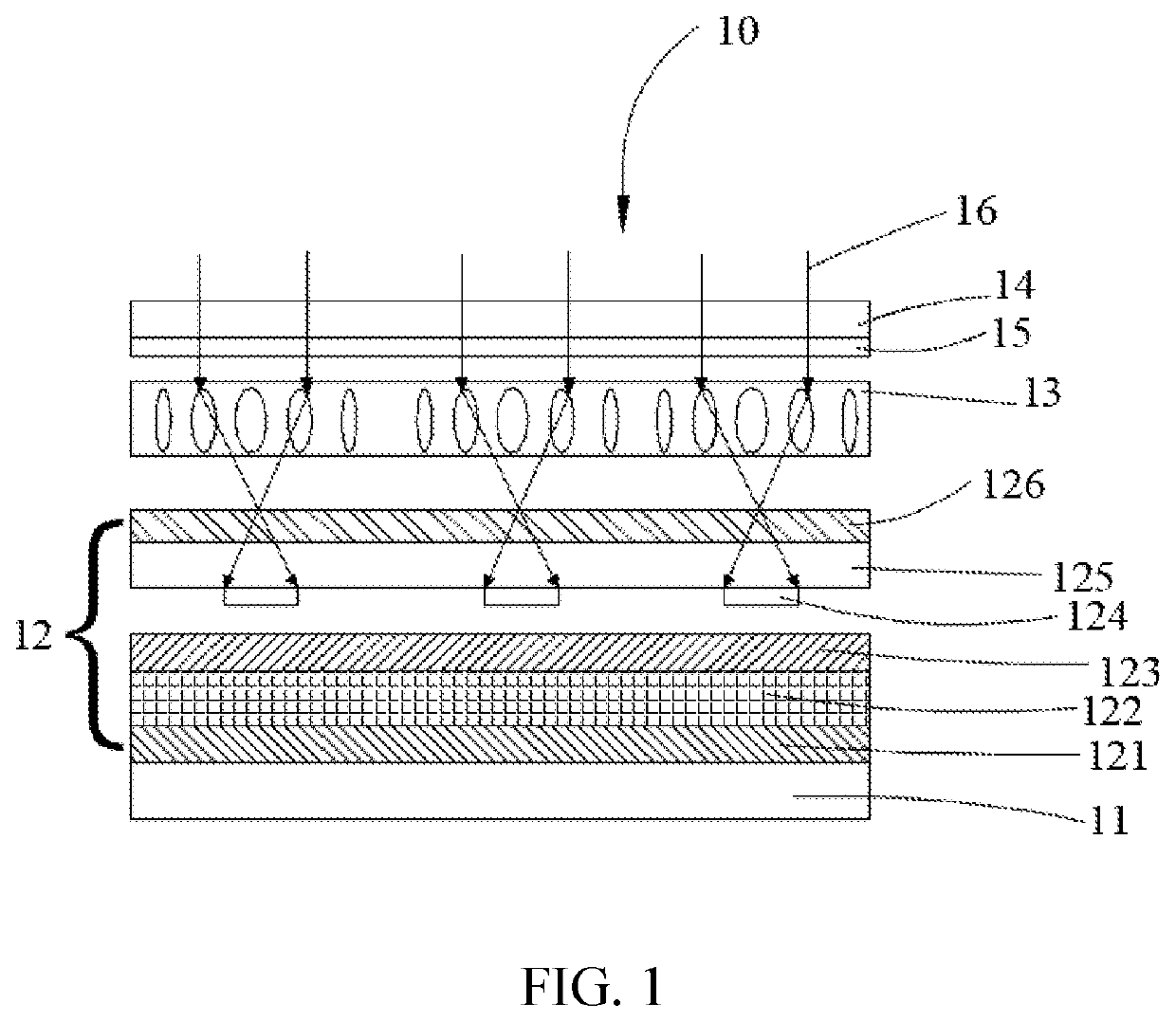
[0038]Please refer to FIG. 1 showing a schematic structural view of an LCD device 10 in accordance with the first embodiment of the present invention. The LCD device 10 is provided with a backlight module 11 disposed at a bottom of the LCD device 10. A bottom polarizer 121 is disposed on the backlight module 11. A TFT layer and a TFT trace 122 are fabricated on the bottom polarizer 121. Then, a liquid crystal layer 123 is fabricated on the TFT layer and the TFT trace 122. A color filter plate 125 is disposed on the liquid crystal layer 123. A fingerprint recognition sensor 124 is provided below the color filter plate 125. A top polarizer 126 is disposed on the color filter plate 125.
[0039]The bottom polarizer 121, the TFT layer and the TFT trace 122, the liquid crystal layer 123, the color filter plate 125, the fingerprint recognition sensor 124, and the top polarizer 126 cooperatively constitute a display module 12. A liquid crystal lens layer 13 is disposed above the display modul...
embodiment 2
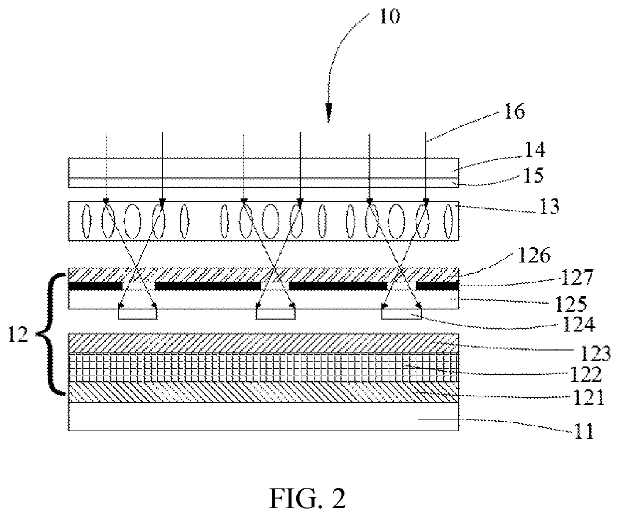
[0043]Please refer to FIG. 2 showing a schematic structural view of an LCD device 10 in accordance with the second embodiment of the present invention. In comparison with the LCD display device 10 in the first embodiment, the LCD display device 10 in the second embodiment is provided with a black mask layer 127 disposed on the color filter plate 125 in the display module 12.
[0044]The lens array of the liquid crystal lens layer 13 corresponds to an array of holes formed by the black mask layer 127. By using lens focusing and pinhole imaging, a utilization of reflected light reflected by a finger can be maximized, thereby increasing recognizability of fingerprint touch. The black mask layer 127 is a black matrix or is made of a black metal, such as metal aluminum and molybdenum oxide.
[0045]The black mask layer 127 is disposed on the color filter plate 125, and is preferably disposed on an upper surface of the color filter plate 125. A position of stacking the black mask layer 127 in a...
embodiment 3
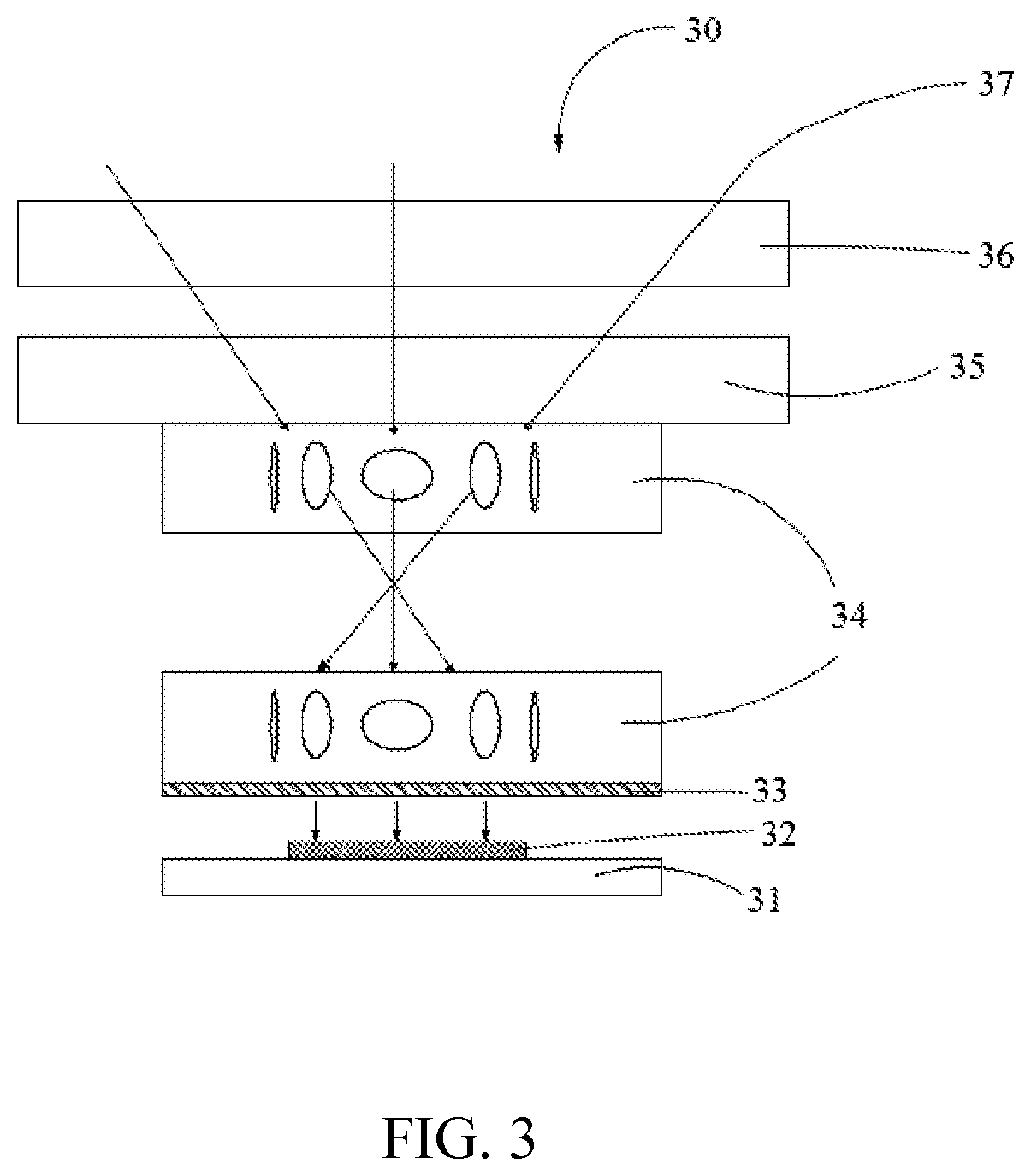
[0046]Please refer to FIG. 3 showing a schematic structural view of an organic light-emitting diode (OLED) display device 30 in accordance with a third embodiment of the present invention. The third embodiment is directed to an OLED display device 30. The OLED display device 30 includes a base substrate and a base substrate trace 31 disposed on a bottom of the OLED display device 30. A fingerprint recognition unit 32 is disposed on the base substrate and the base substrate trace 31. A two-layered liquid crystal lens layer 34 is disposed above the fingerprint recognition unit 32. An OLED display 35 is disposed on the two-layered liquid crystal lens layer 34. A cover glass 36 is disposed on the OLED display.
[0047]The fingerprint recognition unit of the OLED display device includes a fingerprint recognition sensor.
[0048]The two-layered liquid crystal lens layer 34 is configured to operate in a lens state when the fingerprint recognition unit is operating, and two-layered liquid crystal...
PUM
 Abstract
Description
Claims
Application Information