Remotely controlling a hydraulic system

a hydraulic system and remote control technology, applied in the field of performing an action, can solve the problems of affecting the operation of the technician, affecting the health and safety of the technician, and causing the technician to be prone to dangerous operations,

Pending Publication Date: 2022-08-18
KOODAIDERI INNOVATION & TECH PTY LTD
View PDF14 Cites 0 Cited by
  • Summary
  • Abstract
  • Description
  • Claims
  • Application Information

AI Technical Summary

Problems solved by technology

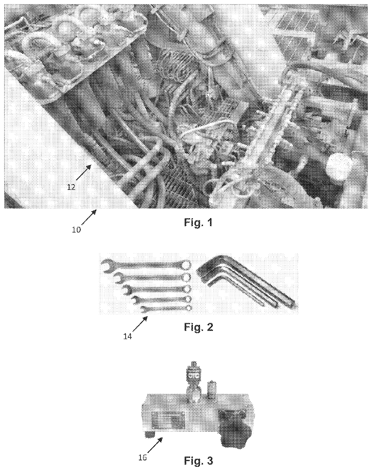
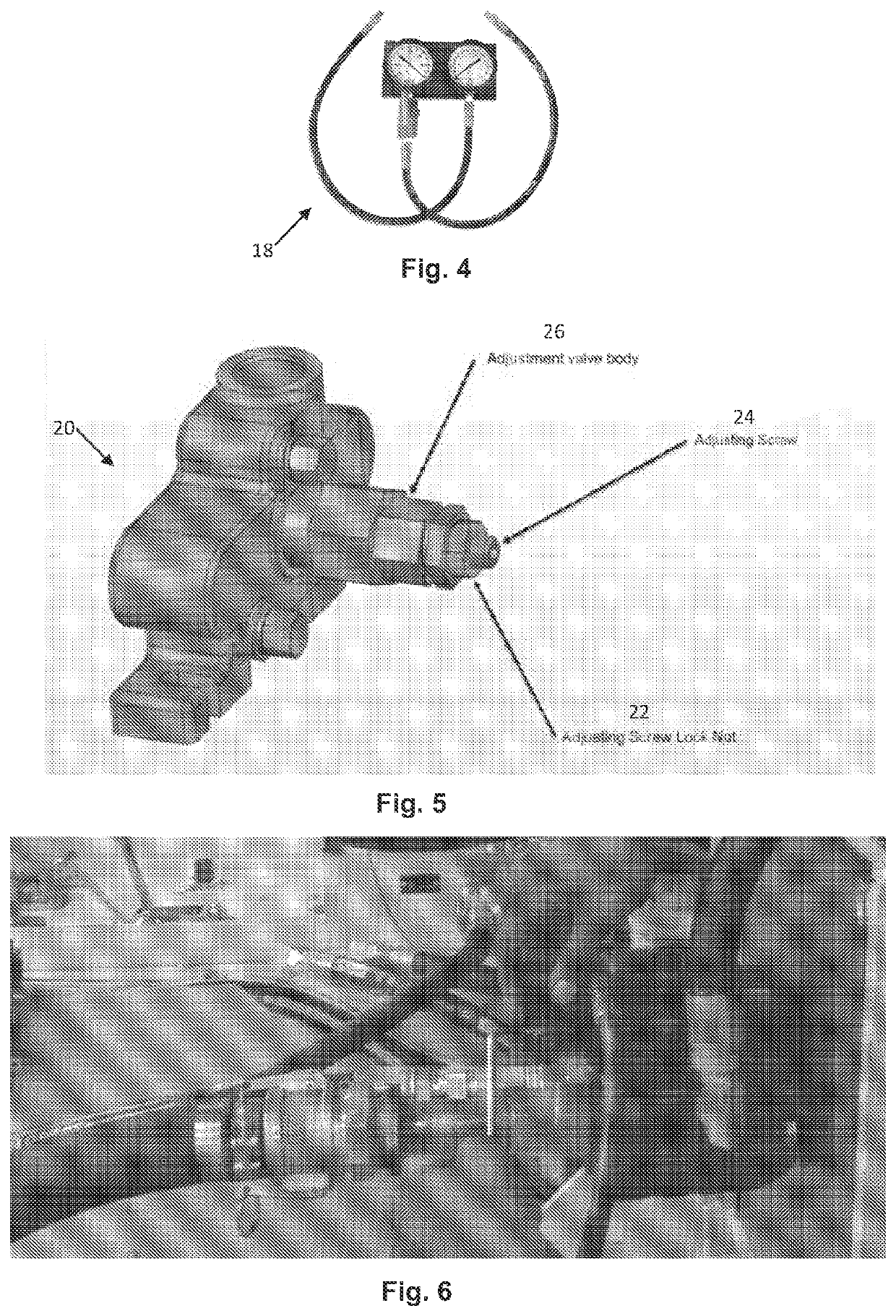
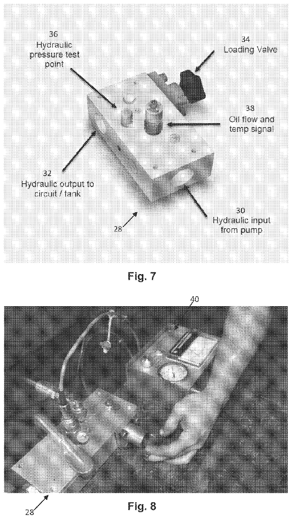
These adjustments are traditionally performed by trained technicians or mechanics using hand tools 14, as depicted in FIG. 2, for example, and hydraulic testing equipment (including flow meters 16, as depicted in FIG. 3, and pressure gauges 18, as depicted in FIG. 4, for example) and are often performed in hazardous locations surrounded by multiple high-pressure hydraulic circuits, inside moving machinery, and with ambient temperatures often exceeding 60° C. Undertaking such work, in such an environment, is both unpleasant and dangerous for the technicians involved.
As depicted in FIG. 8, manually increasing the pressure in the hydraulic circuit by using the loading valve 34 often situates the technician near high pressure hydraulic circuits, high ambient temperatures and high noise environments inside operating equipment, thereby posing a significant risk to the health and safety of the technician.
Some of the issues associated with this method of tuning include:it being a potentially hazardous operation for the technician as the control / pump room contains the hydraulic system (which may be running / operating up to 5000 PSI through the pumps / valves thereof).
If a malfunction occurs, the technician may be seriously injured (by burns and / or hydraulic injection, for example);discomfort for the technician involved in the operation due to conditions of high heat / temperature and poor ventilation in the control room;it being a tedious process requiring the technician to access the control room to perform tuning and check the status of the hydraulic system; andit being a time consuming process and providing no access to live data from the hydraulic system.
This requires the technician to physically enter the control / pump room to make the necessary adjustments, increasing their exposure to potential risks / discomforts including risk of hydraulic incident and heat exposure.
Accordingly, the traditional method of tuning such machines is dangerous, time consuming, and inefficient.

Method used


Image

  • Remotely controlling a hydraulic system
  • Remotely controlling a hydraulic system
  • Remotely controlling a hydraulic system

Examples


Embodiment Construction

[0138]It should be noted in the following description that like or the same reference numerals in different embodiments denote the same or similar features.

[0139]In FIGS. 9 and 10, there is depicted a first embodiment of a system 110 for performing an action in accordance with aspects of the present invention, arranged according to a first operational set up and a second operational set up, respectively.

[0140]In the embodiment described, the action is performed on, in respect of, in association with, and / or in relation to, an other system 112, which may be referred to as a second system, comprising a hydraulic pump 114.

[0141]As will be described in further detail, the system 110 is operable to allow a technician 116, being a user or operator of the system 110, to perform a plurality of actions or operations comprising hydraulic system testing and adjustments on, or in respect of, the hydraulic pump 114. That is to say, to conduct hydraulic tuning of the hydraulic pump 114.

[0142]Part...


PUM


Abstract

In one aspect, an actuator for actuating a device comprises driving means adapted to be operatively connected to the device, and operable to receive a reaction element for engaging the device. The driving means further comprises an output adapted to be operatively engaged with the device for actuation of the device whilst the reaction element is engaging the device.

Description

CROSS-REFERENCE TO RELATED APPLICATIONS[0001]This application is a continuation of U.S. patent application Ser. No. 17 / 427,258 filed Jul. 30, 2021, which is a U.S. national phase of PCT / AU2020 / 050103 filed Feb. 7, 2020, which claims the Convention priority of AU 2019900428 filed Feb. 11, 2019. The entire disclosure of each of the above-identified applications is hereby incorporated herein by reference.FIELD OF THE INVENTION[0002]The present invention relates generally to performing an action.[0003]The present invention will be described with particular reference to remotely performing a hydraulic tuning action in respect of a system comprising a hydraulic circuit.[0004]However, it will be appreciated that the invention is not limited to this particular field of use, it may be used in respect of other systems, and for performing one or more actions, and for additional and / or alternative purposes.BACKGROUND[0005]Any discussion of the background art throughout the specification should ...

Claims


Application Information

Patent Timeline
Patent Type & Authority Applications(United States)
IPC IPC(8): G05B19/042F15B21/02
CPCG05B19/042H04W4/38F15B21/02G05B19/0405G05B19/0425G05B19/058G05B19/46G05B21/02G08C2200/00G08C2201/30G08C2201/42G05B2219/41309F15B21/08F15B2211/665F15B19/00F15B2211/20538F15B2211/20546F15B19/002F15B2211/632F15B2211/6323F15B2211/6306F15B2211/6343F15B19/005F15B2211/6309F15B2211/855F15B2211/857F15B2211/85F15B2211/2053G05B2219/15117G05B19/0426E02F9/205E02F9/2267G05B2219/25312
Inventor LEWIS, SHANE RUSSELL
Owner KOODAIDERI INNOVATION & TECH PTY LTD
Why Eureka
Try Eureka