Apparatus for managing cables

a technology for managing cables and cables, applied in mechanical apparatus, other domestic objects, machine supports, etc., can solve problems such as haphazard or dangerous cable positioning, equipment damage, and opportunities for tripping

Inactive Publication Date: 2000-01-11
MICRON TECH INC
View PDF53 Cites 79 Cited by
  • Summary
  • Abstract
  • Description
  • Claims
  • Application Information

AI Technical Summary

Problems solved by technology

Oftentimes these cables lay about in a haphazard or dangerous fashion.
Cables strewn about a room in disarray offer ample opportunities for tripping over, for damaging the equipment to which they are connected, or for harming other equipment in close proximity.
Moreover, cables laying in disarray may make it more difficult and time consuming to find a particular cable or circuit for equipment maintenance periods or during system downtimes. To avoid these problems, most of the current solutions to cable management and organization employ rings or trays of rectangular cross-section that hold the cables in place.
These designs work well in some situations, but in some cases they are less than adequate, such as when it is desirable to substantially hide the cables or when space is limited.
A rectangular cross-section tray design may not fit snugly into an area (e.g., a corner) where cables will run, or may require too much space down the length of one side of an area to be sufficiently usable.

Method used


Image

  • Apparatus for managing cables
  • Apparatus for managing cables
  • Apparatus for managing cables

Examples


first embodiment

the Invention

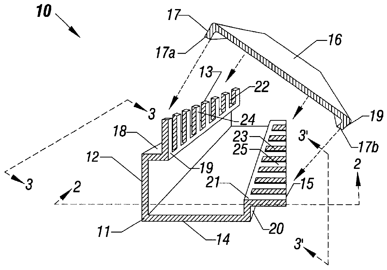
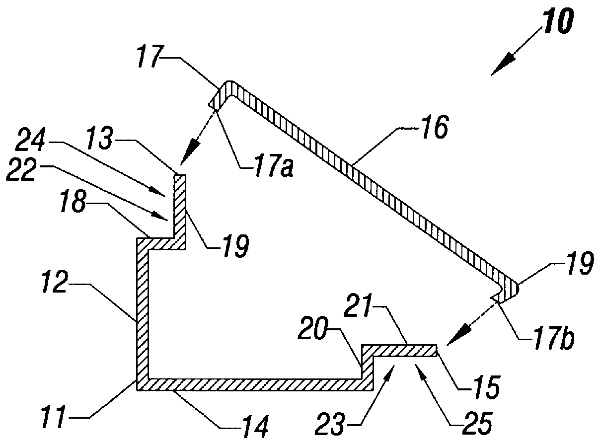
FIG. 1 shows a perspective representation view and FIG. 2 shows an end view along line 2--2 in FIG. 1 of a cable management device 10 in accordance with a first embodiment of the invention. The cable management device 10 has a somewhat triangular cross-section. The cable management device 10 includes a tray portion 11 having a rear surface or segment 12 angularly disposed relative to a bottom surface or segment 14 which, in this particular embodiment, are continuous with each other at approximately a right angle. Angles other than a right angle may be employed in alternative embodiments.

The cable management system 10 also includes a removable cover 16 which may be affixed at snapable or bendable edges 17a and 17b to both upper 13 and lateral 15 edges of the tray 11 which are located distally from the surfaces 12 and 14, respectfully. The edges 17a and 17b of the cover 16 are curved and snap or fit over a portion of the upper 13 and lower 15 ends of the tray 11 over the ...

second embodiment

the Invention

In accordance with a second embodiment of the invention, shown in a perspective view in FIG. 6, a device 10' includes a tray 11' and a cover 16' having ports or connectors 27 (e.g., network ports). The tray 11' may be similar to tray 11 in the device 10 with the notches 21 and 22 in sections 19 and 21, or one or both sets of the notches 19 and 21 may be omitted (not shown). The device 10' is otherwise similar to the device 10. The ports 27 in the cover 16' may be, for example, RJ-45 network ports, RJ-11 ports, GPIB ports, serial or parallel ports, DB-9 or DB-25 connectors, or 34 or 50 pin, or other connectors for connecting network cables external to the device 10' to the cables 26 (which may be network cables) which are carried within the device 10', as shown in FIG. 7 in an end view (with the cover 16' closed).

In FIG. 7, one of the cables 26 is shown coupled by a connector 28 to the port 27 and an external cable 29 is also coupled by a connector 29a to the port 27 so ...


PUM


Abstract

The invention, in one embodiment is a cable management device. The device includes an elongated tray having a first surface and a second surface. The first surface further comprises a notched section continuous with the first surface; and a first end on the notched section distal from the first surface. The second surface further is continuous with the first surface and angularly disposed relative thereto and has a second end. The device also includes a cover attachable to the first end and to the second end.

Description

1. Field of the InventionThe invention relates in general to the field of cable and conduit management and, more particularly, to the organization and distribution of computer cables or other similar items.2. Description of Related ArtComputer systems, for example, personal computers, servers, etc., may be coupled to peripheral and other devices for communicating information such as data, commands, addresses, etc. through a multitude of cables. Oftentimes these cables lay about in a haphazard or dangerous fashion. Cables strewn about a room in disarray offer ample opportunities for tripping over, for damaging the equipment to which they are connected, or for harming other equipment in close proximity. Moreover, cables laying in disarray may make it more difficult and time consuming to find a particular cable or circuit for equipment maintenance periods or during system downtimes. To avoid these problems, most of the current solutions to cable management and organization employ rings...

Claims


Application Information

Patent Timeline
Patent Type & Authority Patents(United States)
IPC IPC(8): F16L3/26F16L3/00H02G3/04
CPCF16L3/26H02G3/0425H02G3/045
Inventor HOWELL, MATTHEW G.
Owner MICRON TECH INC
Why Eureka
Try Eureka