Bracket for attachment of optical devices and other support apparatuses to support objects

a technology for supporting objects and optical devices, applied in the field of support brackets, can solve the problems of affecting the use of certain optical devices by outdoor users

US6021984AInactive Publication Date: 2000-02-08MILLS JAMES EVERETT
11 Cites 46 Cited by

Patent Information

Authority / Receiving Office
US · United States
Patent Type
Patents(United States)
Current Assignee / Owner
Publication Date
2000-02-08
Estimated Expiration
Not applicable · inactive patent

Smart Images

  • Figure 1
    Figure 1
  • Figure 2
    Figure 2
  • Figure 3
    Figure 3
Patent Text Reader

Abstract

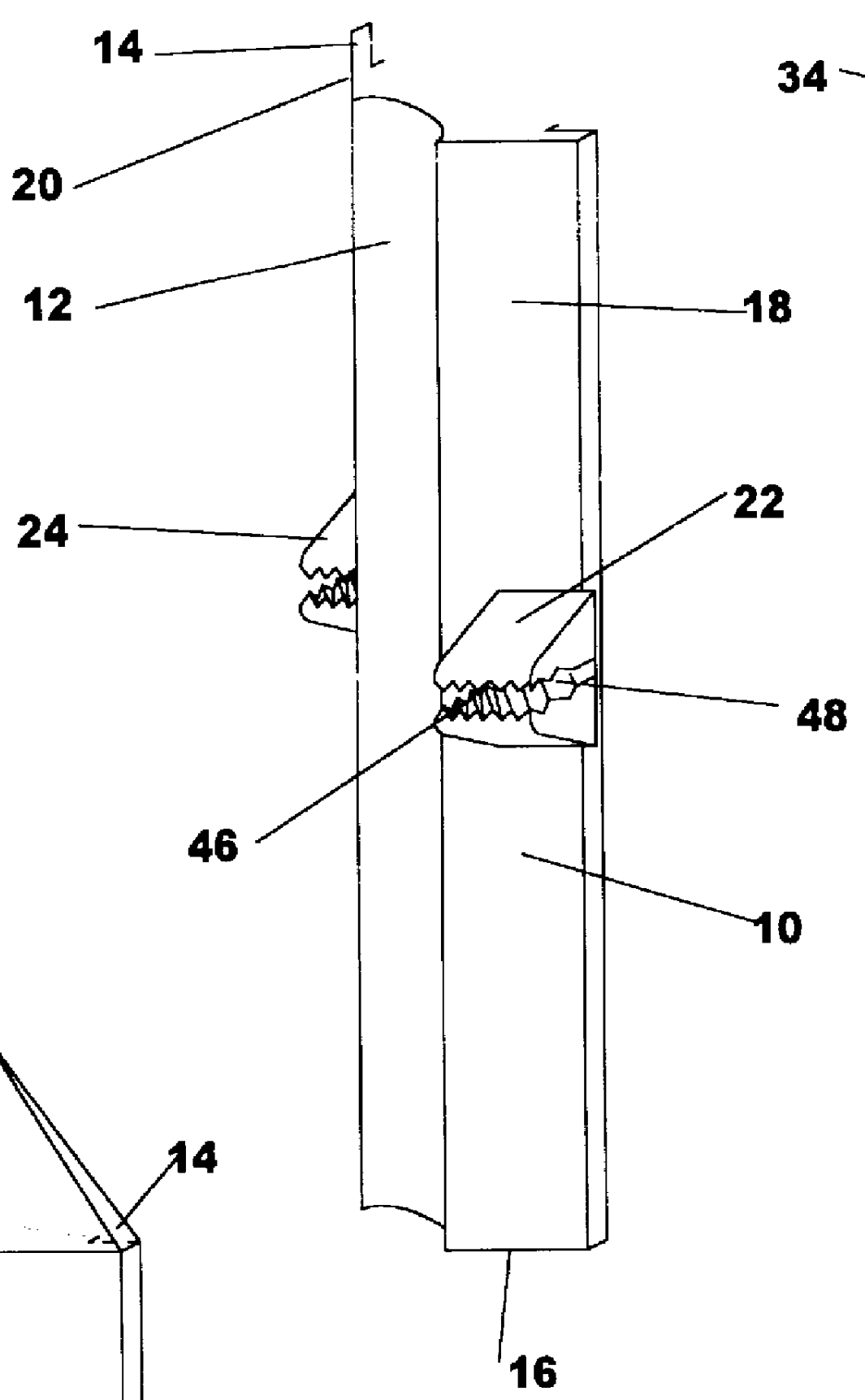
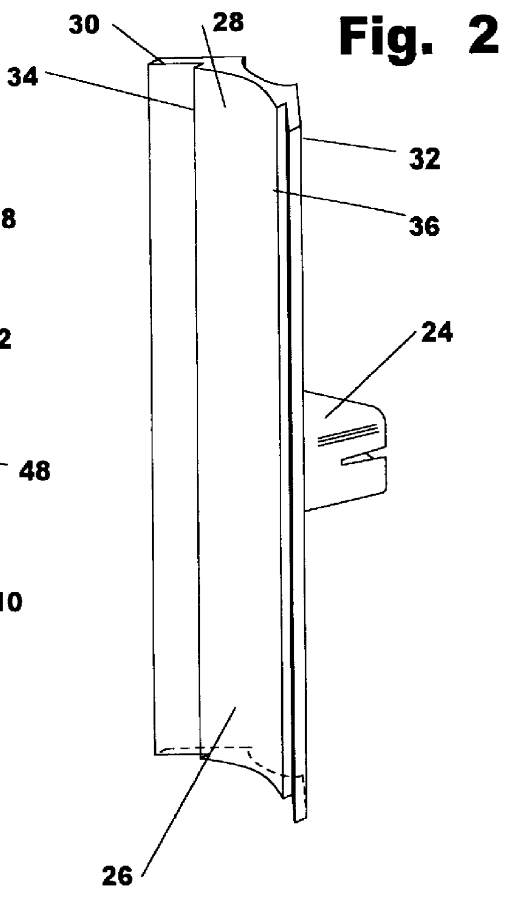
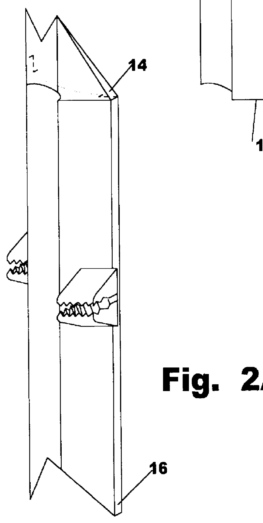
An improved device for attachment of support apparatuses such as a tripod, support accessory, adjustable ball and socket support arms, and the like, to supplemental support objects such as a tree or limb, post or rail or other environmental objects, is herein provided. Convenient portable support of cameras, spotting scopes, optical devices and other devices is enhanced by enabling placement at usable heights, locations, and positions beyond the capabilities of the support apparatus alone. Shown as generally rectangular in shape, the support attachment device has a support apparatus side and supplemental support side, and an upper and lower end. FIG. 1 shows the support apparatus side 10 of the support attachment device. A support receiving groove 12 begins at the upper end 14 and ends at the lower end 16. Support receiving groove 12 divides a first support apparatus face 18 and second support apparatus face 20. A first rope clenching cleat 22 is contained upon first support apparatus face 18 and a second rope clenching cleat 24 is contained upon second support apparatus face 20. First rope clenching cleat 22 and second rope clenching cleat 24 are passive means for tightly clenching a flexible binding means such as common rope or the like. A rope placed within a rope clenching cleat is tightly bound without the need for a buckle requiring manual manipulation. No additional manually operated clamp or buckle is needed. By using common rope as a flexible means or secure attachment, the user is not limited by finite lengths of normal straps or finite sizes of normal clamps, but instead enabled to easily add to length as needed.
Need to check novelty before this filing date? Find Prior Art

Description

1. Field of InventionThe present invention relates to support brackets for attachment to supplemental support objects, and more particularly to such brackets having means for support of optical devices and the like.2. Description of Prior ArtBrackets intended to act as a connector between a variety of support apparatuses and support objects are well known. Typically such brackets will either attach to such support objects by traditional means such as clamps, screws, bolts or like fasteners, magnets, adhesive, or the like, as well as flexible binding means.Known brackets that utilize flexible binding means will typically utilize a variety of strapping materials. Such strapping materials will typically be secured by traditional clamping or clenching means such as buckles, slides, turnbuckles, or the like. Occasionally means such as chains and beaded or knotted material combined with catches such as hooks or chain notches will be employed as a clenching means. Such means have served mo...

Examples

Embodiment Construction

Description

An improved device for attachment of support apparatuses to supplemental support objects is herein provided. Shown as generally rectangular in shape, the support attachment device has a first and second side and a first and second end.

FIG. 1 shows the support apparatus side 10 of the support attachment device. Support receiving groove 12 begins at the upper end 14 and ends at the lower end 16. Support receiving groove 12 divides a first support apparatus face 18 and second support apparatus face 20. A first rope clenching cleat 22 is contained upon first support apparatus face 18 and a second rope clenching cleat 24 is contained upon second support apparatus face 20. First rope clenching cleat 22 and second rope clenching cleat 24 contain rope receiving channel 44. Rope receiving channel 44 has sharply corrugated walls which form rope gripping ridges 46. The angle of declination of rope gripping ridges 46 is compound, running from the top of rope receiving channel 44 to t...