Kicking exerciser for martial arts

Inactive Publication Date: 2000-02-29
FUENTES JOE A
View PDF13 Cites 57 Cited by
  • Summary
  • Abstract
  • Description
  • Claims
  • Application Information

AI Technical Summary

Problems solved by technology

A decided disadvantage to the ankle weights is when the user "throws" a kick, the weight tends to stretch the leg which is already at the maximum extension and can cause injury.

Method used


Image

  • Kicking exerciser for martial arts
  • Kicking exerciser for martial arts
  • Kicking exerciser for martial arts

Examples


Embodiment Construction

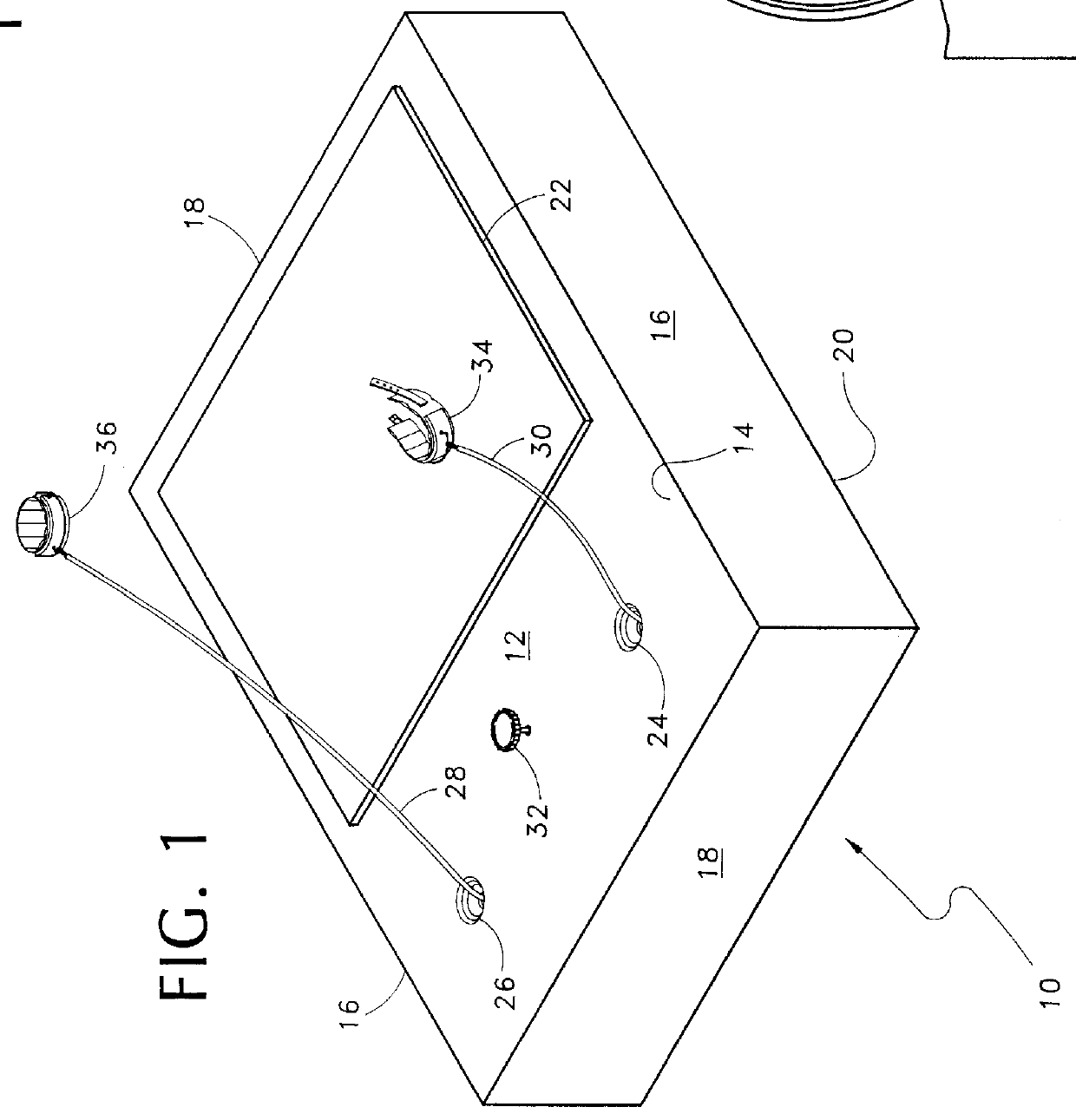
Referring now to FIG. 1, the invention is shown generally at 10 and consists of a housing 12 with a top wall 14 and parallel upstanding side walls 16 and parallel upstanding end walls 18. A bottom wall 20 is a flat planar surface parallel to top wall 14. The top surface includes an area 22 for the user to stand while exercising. The area may be covered with a surface material that inhibits slipping in that most kicking exercise is performed with the feet uncovered and perspiration on a slick surface is conducive to slipping and falling. Apertures 24 and 26 through top wall 14 allow cables extend and retract from the control mechanism located within the housing 12. An adjustment knob 32 is located between apertures 24 and 26 and is connected to the friction brake located in the housing. Cables 28 and 30 have, removably connected to their ends, ankle straps 34,36 which are worn by the user during the kicking exercise.

Concerning FIGS. 2 and 3, cables 28 and 30 are stored on reels 38 an...


PUM


Abstract

The invention is an exercise apparatus for athletes who engage is sports that require a strong, quick kick. A pair of cables extend from a platform and contain cuffs for strapping to the athletes ankle. Below the platform is a mechanism, including a reel for storing each cable, mounted on a common shaft, through a one way clutch. Each reel is connected to a recoil spring which retracts the cable when any force withdrawing the cable is relaxed. An adjustable friction brake is attached to the common shaft for controlling the force required to withdraw the cable from the stored condition.

Description

1. Field of the InventionThis invention relates generally to exercise equipment and more particularly to an exercise apparatus that will condition and strengthen the legs of a person engaged in the martial arts.2. Description of the Prior ArtSome sports involve using the feet for kicking as well as the hands for competitive engagement. Two of those sports include Kickboxing and Karate. The object is to down your opponent by blows with the feet as well as the hands. The competitive edge in such a sport is found in speed and strength. The development of a good kick takes years of practice, much of it the form of repetitive kicking exercises. Quicker and stronger kicks can be developed with resistance, that is working the muscles while actually throwing the kick. Currently, some athletes train for kicking using strap on ankle weights for resistance, which is superior to kicking the air or punching bag in so called impact training which tends to develop only certain muscles and leaves o...

Claims


Application Information

Patent Timeline
Patent Type & Authority Patents(United States)
IPC IPC(8): A63B21/04A63B21/02A63B21/00A63B23/04A63B69/00
CPCA63B21/04A63B21/1426A63B21/153A63B23/04A63B69/004A63B21/4013A63B2244/10
Inventor FUENTES, JOE A.
Owner FUENTES JOE A
Why Eureka
Try Eureka