Ball and socket joint with internal stop

a technology of ball and socket joint and stop, which is applied in the direction of mechanical equipment, instruments, optical elements, etc., can solve the problems of pin breakage, pin breakage, and inability to allow much pivotal movement, so as to limit the relative pivoting motion of the connector, the effect of minimizing the possible decoupling of the connector

Inactive Publication Date: 2000-03-28
LOCKWOOD PROD
View PDF96 Cites 284 Cited by
  • Summary
  • Abstract
  • Description
  • Claims
  • Application Information

AI Technical Summary

Problems solved by technology

A disadvantage of conventional connector designs is that it is possible for the ball to be pivoted in the socket to such an extent that the ball connector separates from the socket connector, resulting in a breaking apart of the assembly.
However, the slot does not allow for much pivotal movement and the pin may break.
The stop pin may break resulting in virtually unlimited pivotal movement of the ball relative to the socket.

Method used


Image

  • Ball and socket joint with internal stop
  • Ball and socket joint with internal stop
  • Ball and socket joint with internal stop

Examples


Embodiment Construction

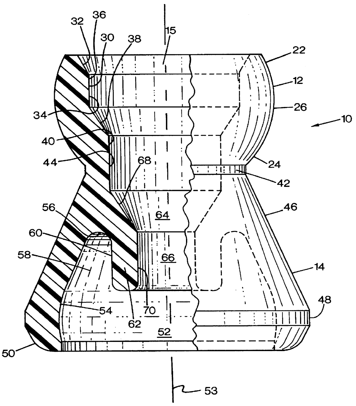
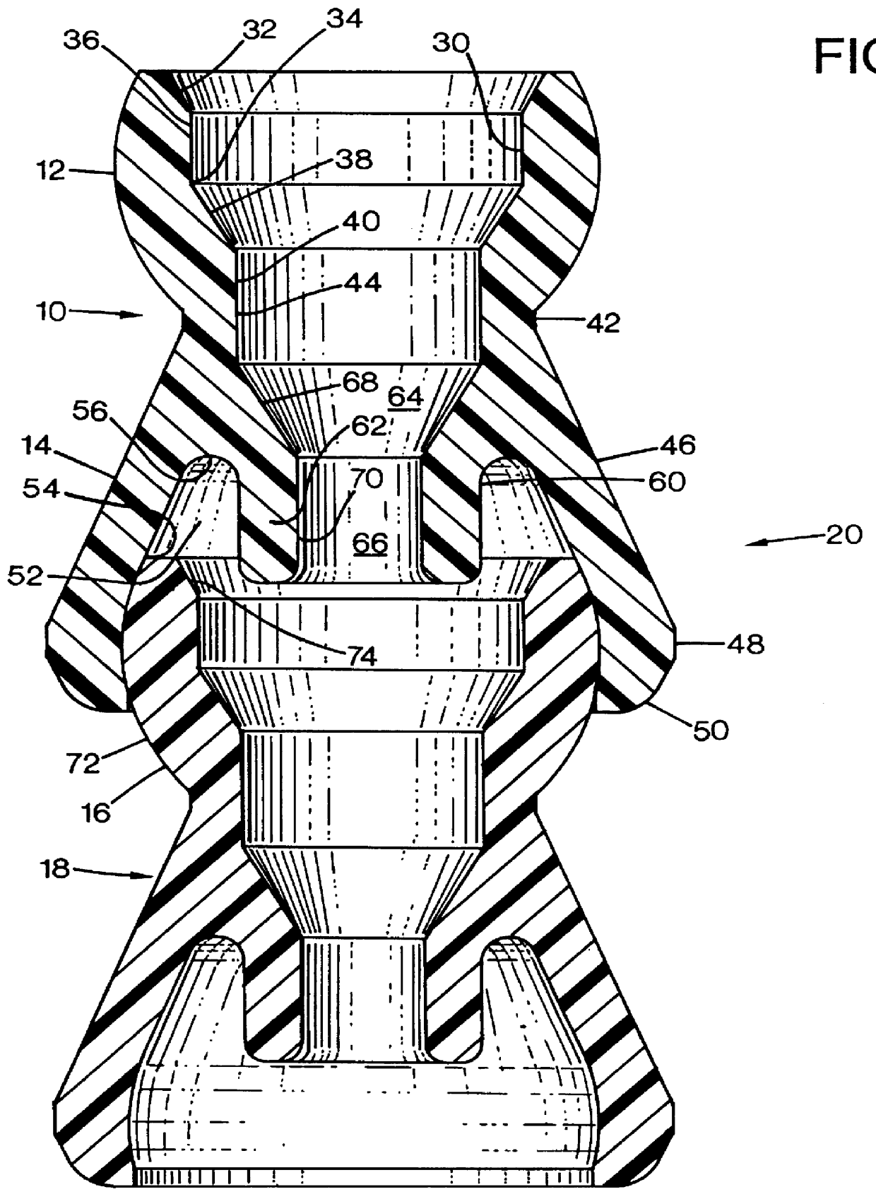
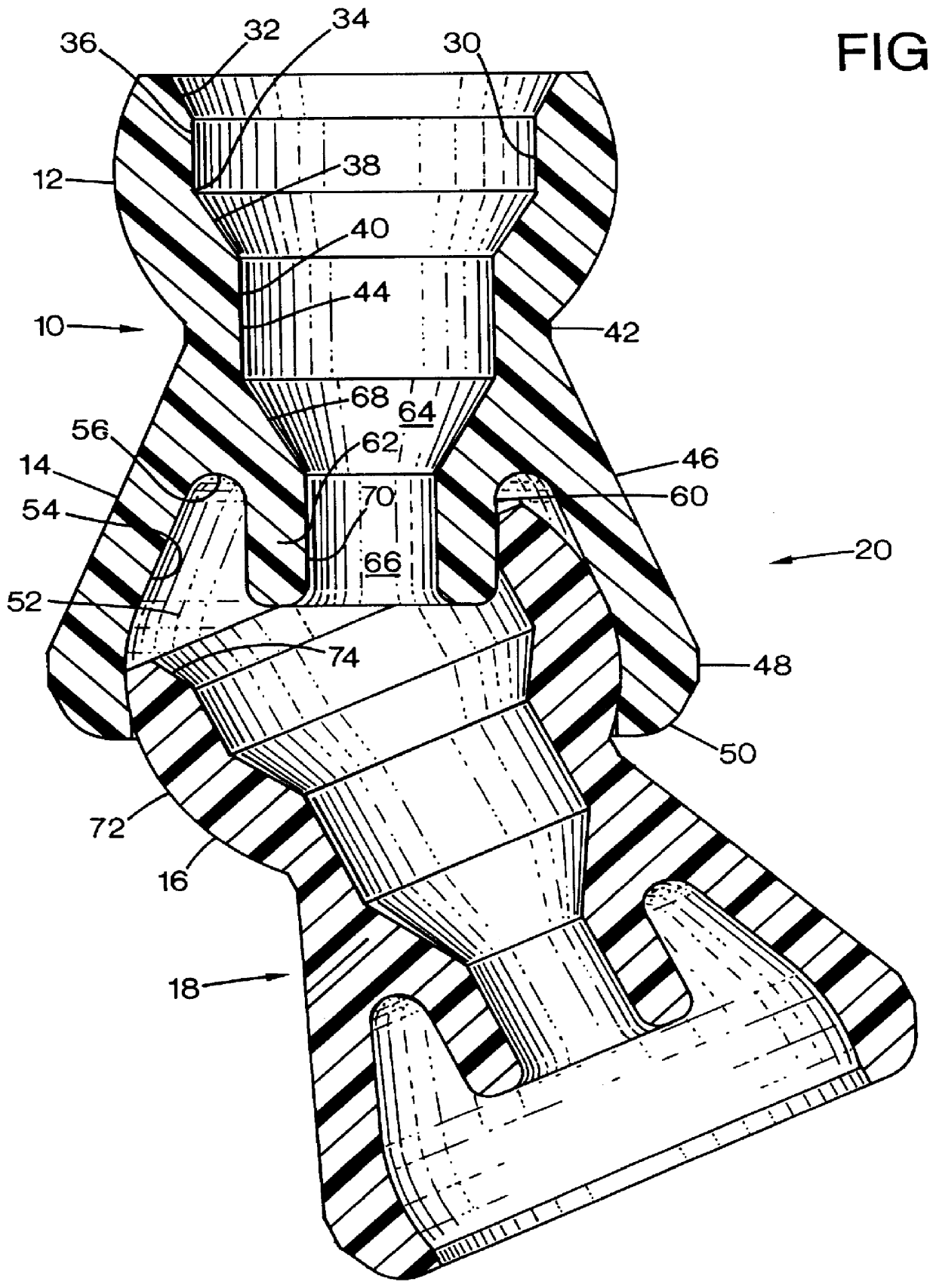
Referring to the FIGS. 1-5, a preferred embodiment of the connector 10 of the present invention includes a body with first and second end portions. A first end portion includes a socket engaging surface such as ball element or surface 12. The second end portion 14 or socket element includes an internal socket defining cavity. The opposite ball and socket elements 12, 14 preferably have a passageway 15 formed therethrough and extending along the longitudinal axis of the connector. The passageway or conduit is used for conveying fluid or for guiding or shielding elements, such as electrical wiring, optical cable, catheters, etc. The socket element 14 is adapted to receive a socket engaging surface such as a ball element 16 of another connector such as connector 18 (see FIG. 2). Thus, the hose connector 10 and hose connector 18, as well as additional similar connectors, may be interconnected to form a flexible hose assembly 20. FIG. 6 illustrates one such assembly of five connectors. A...


PUM

PropertyMeasurementUnit
flexibleaaaaaaaaaa
diameteraaaaaaaaaa
reaction forceaaaaaaaaaa

Abstract

A first connector includes opposite ball and socket elements having a passageway formed therethrough. The socket element has a cavity formed therein for receiving a ball element of a second hose connector to form a hose assembly. A ring is disposed within the cavity for limiting pivotal movement of a ball element inserted therein to minimize the risk that the connectors, and thereby the hose assembly, will separate.

Description

TECHNICAL FIELD OF INVENTIONThe present invention relates to connectors which interconnect into a flexible assembly, such as into a hose, and more particularly to connectors with a stop or limiter for limiting relative pivoting movement of the connectors.Many ball and socket connectors have been developed in the past. A disadvantage of conventional connector designs is that it is possible for the ball to be pivoted in the socket to such an extent that the ball connector separates from the socket connector, resulting in a breaking apart of the assembly.A device for limiting pivotal movement between a ball and a socket is disclosed in U.S. Pat. No. 2,676,806 ('806 patent) to Bachman. The '806 patent discloses a phonograph reproducer arm having a ball fitted within a socket. The ball defines a slot and the socket has a pin attached to its spherical inner surface. Pivotal movement of the ball is limited by placing the ball into the socket so that the pin is captured within the slot defi...

Claims


Application Information

Patent Timeline
Patent Type & Authority Patents(United States)
IPC IPC(8): H02G3/04F16L27/04F16L47/00
CPCF16L11/18G02B6/4461H02G3/0475
Inventor LOCKWOOD, MARK B.
Owner LOCKWOOD PROD
Why Eureka
Try Eureka