Key for insert holders of the blade type

a technology of insert holders and keys, which is applied in the field of key-type insert holders, can solve the problems of affecting the quality of insert holders, the deflection of clamping arms in a way that is difficult to control, and the total rejection of insert holders

Inactive Publication Date: 2000-05-23
SANDVIK INTELLECTUAL PROPERTY AB
View PDF9 Cites 18 Cited by
  • Summary
  • Abstract
  • Description
  • Claims
  • Application Information

AI Technical Summary

Problems solved by technology

The fact that the projections are fixed upon the key shaft means, on one hand, that the user always has to apply a force upon the shaft in order to maintain the clamping arm deflected and the slot widened and, on the other hand, that the amount of deflection of the clamping arm will be effected in a way that is hard to control since the deflection is determined only by a discretionary judgement of the user in applying the force.
Thus, if the user accidentally applies an excessive force upon the shaft there is a risk that the clamping arm will be subjected to a permanent, plastic deformation that in practice means that the insert holder in its entirety has to be rejected.
Sin...

Method used


Image

  • Key for insert holders of the blade type
  • Key for insert holders of the blade type
  • Key for insert holders of the blade type

Examples


Embodiment Construction

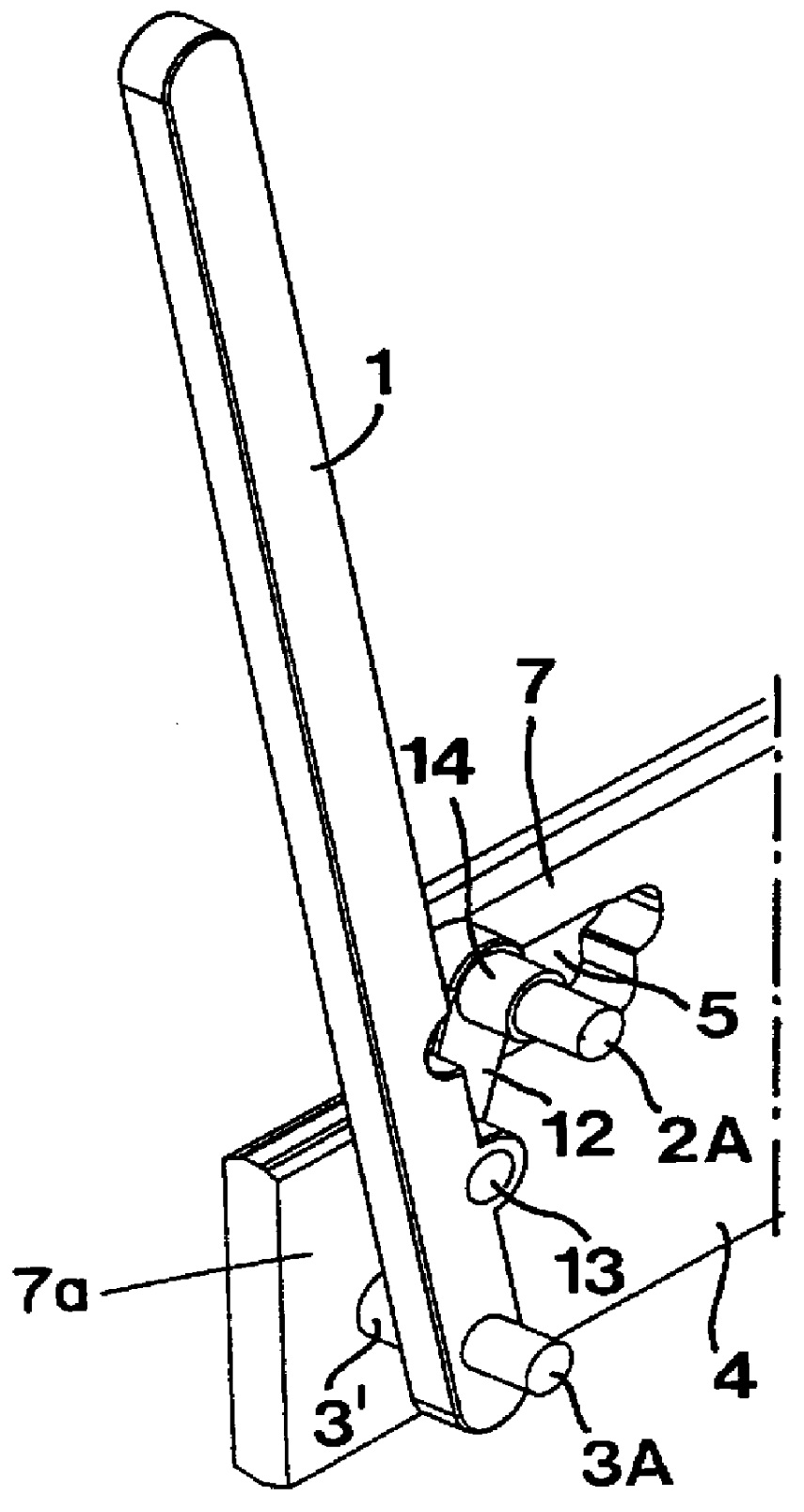
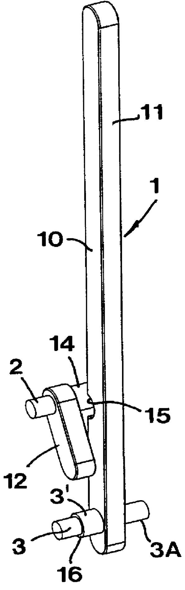
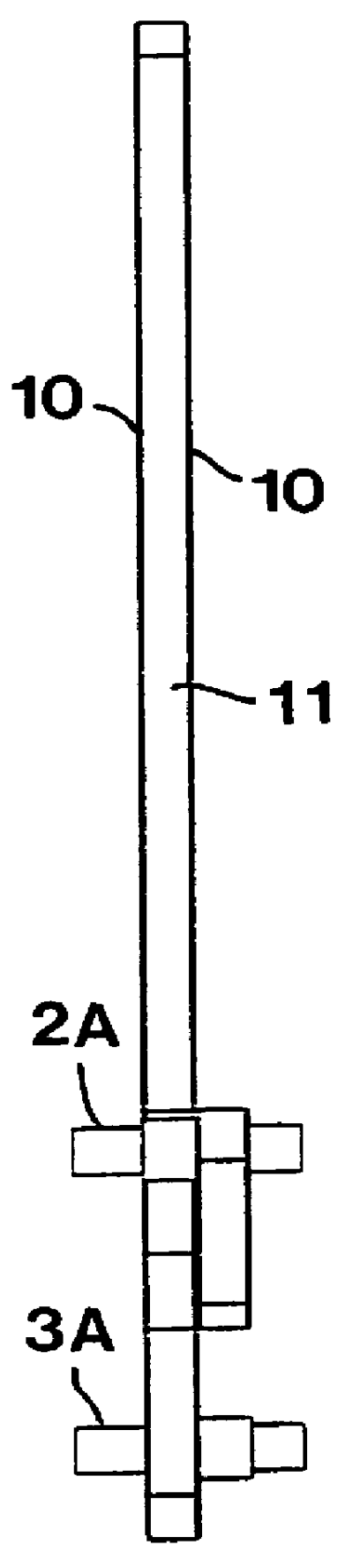
The key shown in FIGS. 1 and 2 includes an oblong shaft 1 and two projections 2, 3 that project laterally from said shaft and define respective abutment surfaces. Before the key is described more in detail, reference is made to FIGS. 4 and 5 that illustrate an insert holder that in a known way is in the shape of a blade-shaped or disc-shaped shaped body 4 provided with a slot 5 that forms a seat for an insert 6. The slot is defined by a base 7a of the blade body and a comparatively narrow clamping arm 7 of the blade body, the arm being elastically flexible relative to the base 7a. The arm 7, due to its inherent elasticity, is able to clamp the insert in the desired position. Seats 8, 9 are recessed in the clamping arm 7 and the base 7a, respectively, as well as in the body 4, said seats 8, 9 defining respective contact surfaces and being adapted to receive the two projections 2, 3 of the key. These seats may either consist of through-going holes or of recesses that open only at one ...


PUM

PropertyMeasurementUnit
Thicknessaaaaaaaaaa
Forceaaaaaaaaaa
Lengthaaaaaaaaaa

Abstract

A slot-widening key for use with insert holders of the kind that includes a blade shaped body having a slot intended to receive an insert. One surface of the slot is defined by an elastically flexible clamping arm for clamping the insert. The key has a shaft with two projections for engaging laterally opening seats in the body and the clamping arm, respectively. One of these two projections is provided on a pivoting link that is pivotably connected with the shaft via a hinge pin. The sum of a first distance between the hinge pin and one of projections, plus a second distance between the hinge pin and the other projection, is larger than the at-rest distance between the seats of the insert holder. Pivoting of the shaft beyond an unstable position of equilibrium thus makes the clamping arm deflect by a predetermined value for widening the slot. The key is self-supporting in the slot-widening position and does not require that the manual force be continuously applied.

Description

The present invention relates to a key for insert holders of the kind that include a blade or disc shaped body having a slot intended to receive an insert, said slot being defined by an elastically flexible clamping arm provided to resiliently clamp the insert in the slot, said key comprising a shaft having two projections for engaging laterally opening seats in the body and the clamping arm respectively, more precisely in order to deflect the clamping arm so as to widen the slot in connection with the mounting and / or dismounting of an insert.PRIOR ARTA clamping key of the kind generally defined above is previously known from FIGS. 6-8 of European Publication No. 0 654 316. In that case two projections are fixed upon a shaft, more precisely quite close to each other in the area of one end of the shaft. The fact that the projections are fixed upon the key shaft means, on one hand, that the user always has to apply a force upon the shaft in order to maintain the clamping arm deflected...

Claims


Application Information

Patent Timeline
IPC IPC(8): B23B27/04B23B27/00B23B27/16B25B33/00
CPCB23B27/04B23B2205/02B23B2260/0785Y10T82/2589Y10T407/2282Y10T407/2286Y10T407/2288
Inventor HANSSON, PER
Owner SANDVIK INTELLECTUAL PROPERTY AB
Why Eureka
Try Eureka