Lubrication systems for scroll compressors

a scroll compressor and lubrication system technology, which is applied in the direction of machines/engines, rotary/oscillating piston pump components, liquid fuel engines, etc., can solve the problems of system efficiency reduction, difficulty in accurate supply of lubricant, and inability to achieve the overall operation of the scroll compressor

Inactive Publication Date: 2000-06-13
CARRIER CORP
View PDF7 Cites 37 Cited by
  • Summary
  • Abstract
  • Description
  • Claims
  • Application Information

AI Technical Summary

Problems solved by technology

However, accurate supply of lubricant has proven challenging.
If too much lubricant is supplied, system efficiency is reduced due to impaired heat transfer in the heat excha

Method used


Image

  • Lubrication systems for scroll compressors
  • Lubrication systems for scroll compressors
  • Lubrication systems for scroll compressors

Examples


Embodiment Construction

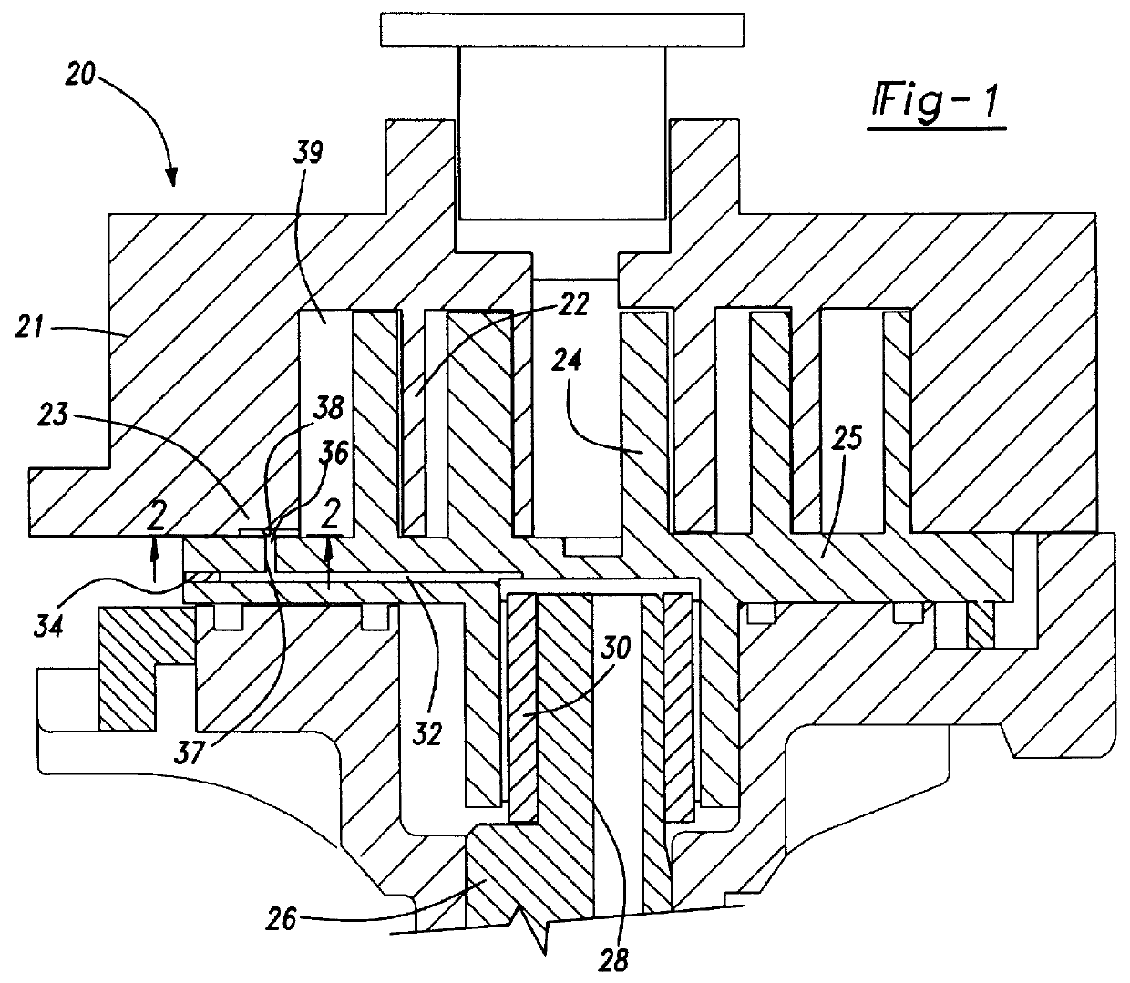
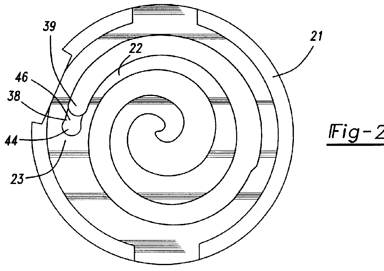
A scroll compressor 20 is shown in FIG. 1 including a fixed non-orbiting scroll member, shown here as a scroll 21 having an outer flange 23 and a spiral wrap 22. An orbiting scroll 25 has its wrap 24 interfitting with the wrap 22 of the fixed scroll 21. As shown, a drive shaft 26 includes a lubricant passage 28 supplying lubricant upwardly through a bearing 30 and to a passage 32 extending through the base of the orbiting scroll 25. As shown, passage 32 is closed by a plug 34 at a remote end. A passage 37 extends through the base and leads to an oil port 36. A recess 38 is formed in the flange 23 of the fixed scroll 22, and communicates with a chamber 39 formed radially inwardly of the flange 23.

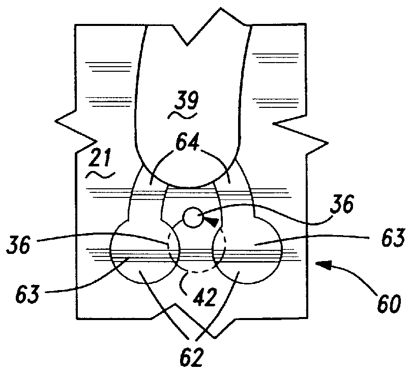
As shown in FIG. 2A, recess 38 includes a circular portion 44 leading to a neck portion 46. While the two portions are shown having the same depth in FIG. 1, they may have differing depths.

The port 36 has its orbiting movements shown at path 42 in FIG. 2B. As shown, the entire orbiting movem...


PUM


Abstract

An improved scroll compressor lubrication system includes a number of embodiments wherein a lubricant port in the orbiting scroll supplies lubricant to the compression chambers throughout its entire orbiting cycle. The lubricant port is aligned with a recess in a flange of the fixed scroll throughout its entire orbiting cycle. In a further embodiment, the lubricant port is exposed to the compression chamber throughout its entire cycle. In other embodiments, the fixed scroll is provided with recesses spaced from each other by approximately 180 DEG . The lubricant port moves sequentially into and out of communication with these spaced recesses to supply lubricant to the compression chambers.

Description

BACKGROUND INVENTIONThis invention relates to a lubrication system for a scroll compressor wherein the amount of lubrication supplied to the compression chambers is closely controlled.Scroll compressors are becoming widely utilized in refrigerant compression applications. As known, scroll compressors contain a fixed scroll and an orbiting scroll which have interfitting spiral wraps. The interfitting spiral wraps define chambers which are compressed as the orbiting scroll moves relative to the fixed scroll. In the prior art, lubricant is supplied to the compression chambers to assist in ensuring smooth operation of the scroll members during compression.However, accurate supply of lubricant has proven challenging. It would be desirable to closely control the amount of lubricant supplied to the chambers. If too much lubricant is supplied, system efficiency is reduced due to impaired heat transfer in the heat exchanger from the insulating effect of the oil. On the other hand, if inadequ...

Claims


Application Information

Patent Timeline
IPC IPC(8): F04C18/02F04C29/02F04C29/00
CPCF04C29/028F04C18/0261
Inventor LIFSON, ALEXANDERKHALIFA, HUSSEIN EZZATBUSH, JAMES W.
Owner CARRIER CORP
Why Eureka
Try Eureka