Ladder stabilizing cross brace

a cross brace and ladder technology, applied in the field of ladders, can solve the problems of no prior art, no invention to prevent the ladder or sections of the ladder from flexing or twisting, and no prior art to prevent the ladder or sections of the ladder from bending or twisting

Inactive Publication Date: 2000-09-12
HUSS MICHAEL A
View PDF18 Cites 17 Cited by
  • Summary
  • Abstract
  • Description
  • Claims
  • Application Information

AI Technical Summary

Problems solved by technology

1. By increasing the span of their bases with outrigger type side braces such as in U.S. Pat. No. 4,147,231 by Cantler, U.S. Pat. No. 4,519,477 by Ralston, U.S. Pat. No. 4,011,926 by Larson and many others.
2. By making the length of the ladder's legs adjustable so as to allow the ladder to stand vertically on uneven terrain conditions, such as in U.S. Pat. No. 5,305,851 by Katson and U.S. Pat. No. 5,462,133 by Merrill.
3. Back braces: Tripod ladders typically have two spreaders holding a single leg to the back of the ladder. U.S. Pat. No. 5,590,739 High, U.S. Pat. No. 4,249,637 Glasglow, U.S. Pat. No. 4,600,080 Forester. These spreaders are positioned one half to two thirds the-way up the ladder and are not sufficiently near the base of the ladder to prevent the back leg or the ladder section from twisting or flexing.
4. Both back brace and outrigger U.S. Pat. No. 4,796,727 Eaton. Another type of ladder is the platform stepladder where the top step is a large platform upon which a person can stand. The platform is pivotally connected to both the front section and the support section. Again the connection is not sufficiently near the base of the ladder to prevent the support section especially from twisting.
None of these inventions prevent the ladder or sections of a stepladder from flexing or twisting.
They do not strengthen the structure of the ladder near the base.
No prior art exists in which a stepladder has been made more stable by connecting the feet or legs to one another near the base.
Nor is there any prior art in which a ladder's outrigger type side braces are connected to the ladder's legs and / or one to another near the base by a triangulated bracing system.
The sections of the stepladder, especially the support section, are not perfectly rigid and can flex.
These spreaders prevent the front and back sections from moving toward or away from one another at the point of the spreaders but they do not prevent the back or front section from flexing or sliding in a plane parallel to each other.
Likewise they do not prevent the left side of the stepladder from moving in a plane parallel to the right side of the stepladder.
And they do not prevent the sections from flexing or twisting above or below the spreaders.
When this happens the two diagonal feet of the stepladder move lower in relation to the other two feet thus making the stepladder stand or rock on two feet rather than stand solidly on four feet, a very unsafe condition.

Method used


Image

  • Ladder stabilizing cross brace
  • Ladder stabilizing cross brace
  • Ladder stabilizing cross brace

Examples


Embodiment Construction

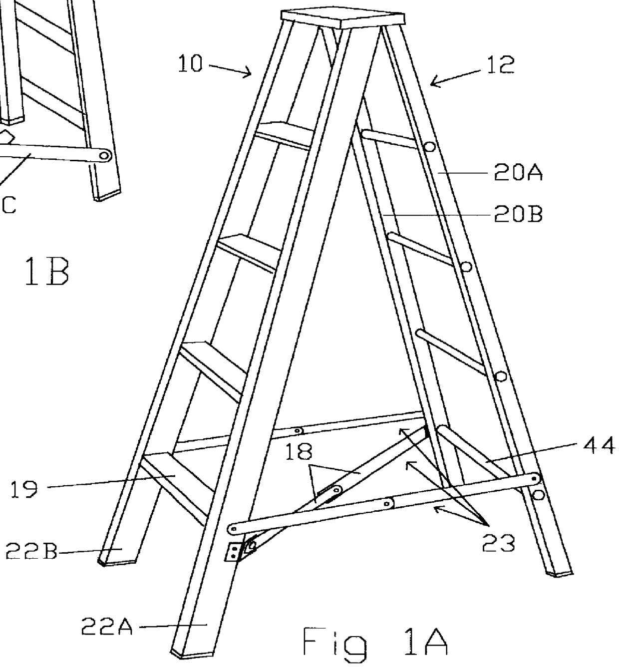
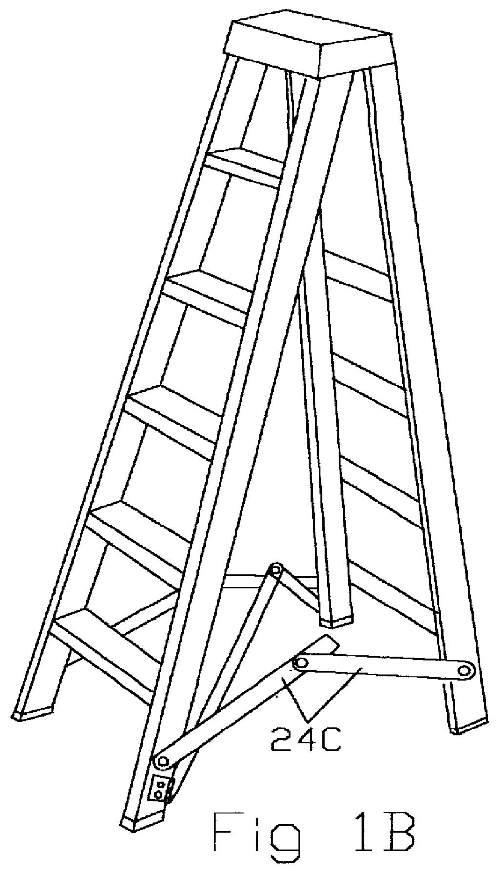
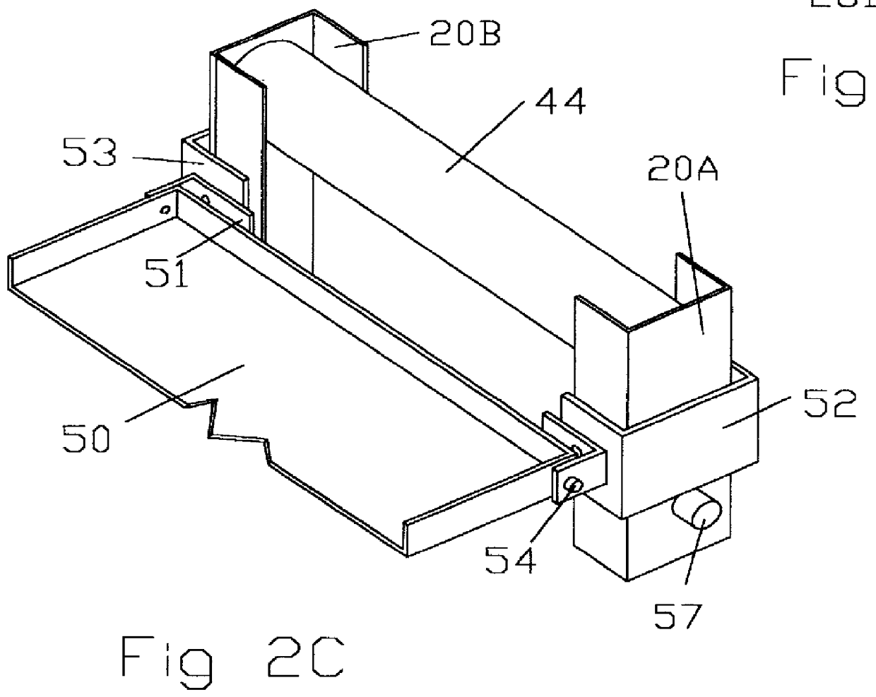
The preferred embodiment of the present invention is illustrated in FIGS. 1A&B and FIGS. 2A&B. FIGS. 1A&B are isometric views of a stepladder fully opened (1A) and partially closed (1B) with a folding triangulated cross bracing system 23 at the base of the stepladder. The cross brace, in it's extended position, connects diagonal legs of the stepladder near the base of the ladder. In addition to folding up like a spreader, the folding cross brace of the referred embodiment must fold sideways into a plane parallel to the front and back sections of the stepladder when the stepladder is folded. This is accomplished by connecting the ends of the folding diagonal cross brace by a compound folding connecting means to the support rail 20A or B and the diagonal side rail 22A or B.

This embodiment includes a folding member diagonal cross brace 18 which connects one pair of diagonal corners of the stepladder. It also includes side spreaders 24C acting as braces between the front section 10 and ...


PUM


Abstract

A ladder stabilizing system having a solid brace (50 or 46) or the combination of side spreaders (24C), the ladder sections (10 and 12), and a diagonal cross brace (18) creating two rigid triangles, the function of which is to prevent the ladder sections from twisting or flexing and therefore make the step ladder or the side braces (70 & 74) of a ladder or step ladder much more stable and will prevent the ladder sections (10 and 22), or extended side braces from twisting or flexing, thereby making the ladder stronger and safer.

Description

BACKGROUND-FIELD OF INVENTIONThis invention relates to ladders, specifically to stabilizers which decrease the possibility of the ladder twisting, slipping or tipping by making the base of the ladder more rigid.DESCRIPTION OF PRIOR ARTPrevious Inventions have increased the stability of ladders in several ways. These methods include:1. By increasing the span of their bases with outrigger type side braces such as in U.S. Pat. No. 4,147,231 by Cantler, U.S. Pat. No. 4,519,477 by Ralston, U.S. Pat. No. 4,011,926 by Larson and many others.2. By making the length of the ladder's legs adjustable so as to allow the ladder to stand vertically on uneven terrain conditions, such as in U.S. Pat. No. 5,305,851 by Katson and U.S. Pat. No. 5,462,133 by Merrill.3. Back braces: Tripod ladders typically have two spreaders holding a single leg to the back of the ladder. U.S. Pat. No. 5,590,739 High, U.S. Pat. No. 4,249,637 Glasglow, U.S. Pat. No. 4,600,080 Forester. These spreaders are positioned one ...

Claims


Application Information

Patent Timeline
Patent Type & Authority Patents(United States)
IPC IPC(8): E06C1/20E06C1/00E06C7/00E06C7/42E06C1/18E06C1/38
CPCE06C1/18E06C1/20E06C1/38E06C7/423
Inventor HUSS, MICHAEL A.
Owner HUSS MICHAEL A
Why Eureka
Try Eureka