Tracheostomy tube with removable inner cannula

a tracheostomy tube and inner cannula technology, applied in the field of tracheostomy tubes, can solve the problems of frequent trauma to the patient, trauma to the trachea, and trauma to the patien

Inactive Publication Date: 2000-10-24
GENERAL ELECTRIC CO
View PDF26 Cites 101 Cited by
  • Summary
  • Abstract
  • Description
  • Claims
  • Application Information

AI Technical Summary

Problems solved by technology

Because of the rigidity of the tube and the hardness of the material, trauma to the patient is frequently inflicted when the tube is inserted into the trachea.
In like fashion, the fenestrations or openings in the upper surface of the tube cause trauma to the trachea, as well, because of the sharp edges created by probing the fenestration.
These additional features also tend to cause trauma to the patient during the insertion and / or manipulation of the tracheostomy tube.

Method used


Image

  • Tracheostomy tube with removable inner cannula
  • Tracheostomy tube with removable inner cannula
  • Tracheostomy tube with removable inner cannula

Examples


Embodiment Construction

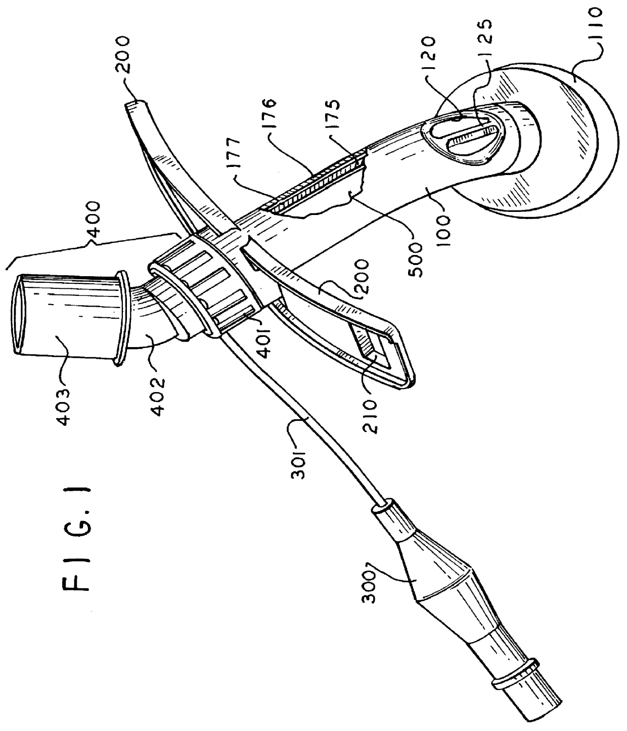
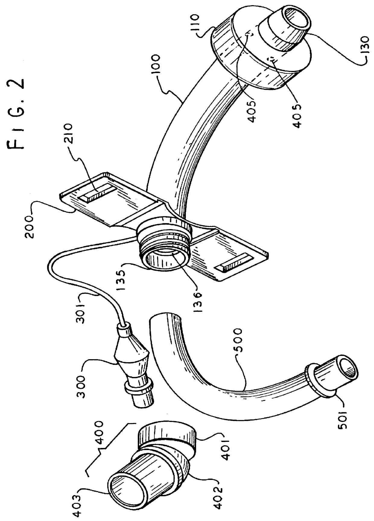
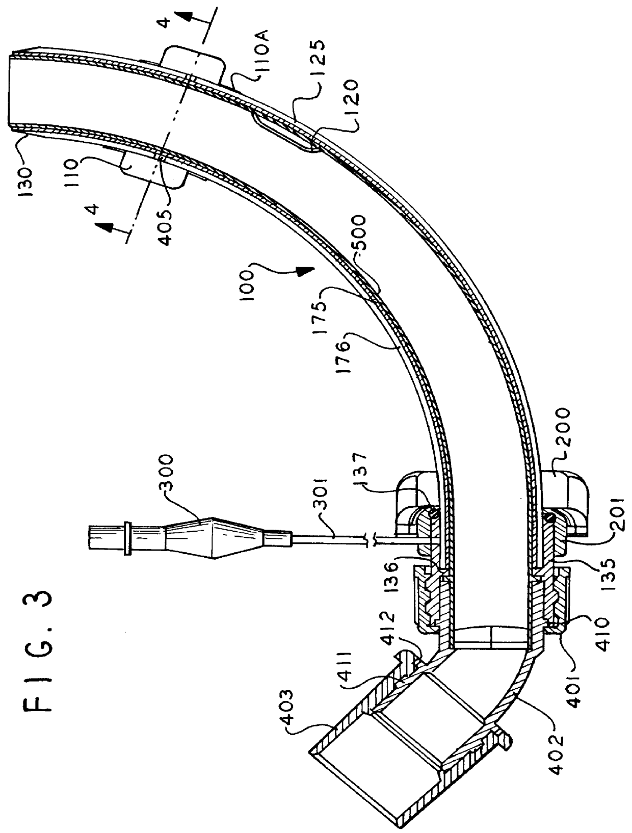
Referring now to FIG. 1, there is shown a partially broken away, oblique view of one embodiment of a composite tracheostomy tube also referred to as a composite tracheal tube (or simply a composite tube) fabricated in accordance with the instant invention. In this embodiment, the tube 100 is an arcuate shaped device of conventional configuration. However, the tube 100 is a composite tube with a rigid inner tube 175 and a relatively soft outer tube 176. Ducts or channels 177 are formed between the inner and outer tubes 175 and 176, as described in greater detail infra.

The arcuate composite tube includes an inflatable balloon or cuff 110 adjacent one end shown in the inflated status. Obviously, when the cuff 110 is not inflated, it is substantially coplanar with the outer surface of the tracheal tube 100.

The tracheal tube 100 includes one or more openings 120 also known as fenestrations. The fenestrations pass completely through the wall of the tube 100 and can be used for non-assiste...


PUM


Abstract

A composite tracheostomy tube or cannula comprising a rigid inner tube and a relatively soft outer tube. One or more ducts or chambers are formed between the outer surface of the inner tube and the inner surface of the outer tube. A sealing or mounting flange is attached to the composite tube adjacent one thereof. A balloon or inflatable cuff is attached to the outer surface of the outer tube adjacent the opposite end of the composite tube. A conduit for connection to a fluid source is provided to selectively inflate and / or deflate the inflatable cuff. An inner tube or cannula is removably inserted into the tracheostomy tube. The inner cannula includes a preferred gripping device at the proximal end thereof.

Description

1. Field of the InventionThe present invention relates to respiratory circuits, in general, and, more particularly, to tracheostomy tubes comprising a composite outer cannula and a removable inner cannula.2. Prior Art StatementTracheostomy tubes are well-known in the art. It is also well-known that a two part tracheostomy tube is used so that if the tracheostomy should be occluded by mucous or phlegm, the tracheostomy tube airway can be cleaned by removing the inner cannula, see U.S. Pat. No. 4,817,598, to D. LaBombard, for example.In the past, the tracheostomy tube has been made of a relatively rigid plastic material such as ABS plastic or the like. These tubes are made according to ASTM or ISO standards which are well-known in the industry. The existing tracheostomy tubes comprise a bent or arcuate tube with a 15 millimeter (or similar) connection at one end which is connected to a breathing circuit or the like. These tubes include flanges at the proximal end thereof for attachmen...

Claims


Application Information

Patent Timeline
Patent Type & Authority Patents(United States)
IPC IPC(8): A61M16/04
CPCA61M16/04A61M16/0427A61M16/0497A61M16/0465A61M16/0434A61M16/0825A61M16/0475
Inventor MONGEON, DOUGLAS R.
Owner GENERAL ELECTRIC CO
Why Eureka
Try Eureka