Endodontic instrument

Inactive Publication Date: 2001-01-16
MANI INC
View PDF6 Cites 27 Cited by
  • Summary
  • Abstract
  • Description
  • Claims
  • Application Information

AI Technical Summary

Problems solved by technology

Therefore, such treatments require skills and create various high level demands to performance and characteristics of files.
Therefore, the file provides high resistance against twisting and bending, but has a smaller rake angle (angle between the blade 51a and the circle), bad property of cutting and removal of cut chips, a lower traceability to a root canal.
However, the resistance against bending and twisting of a file is too low to transfer the force of the dentist t

Method used


Image

  • Endodontic instrument
  • Endodontic instrument
  • Endodontic instrument

Examples


Embodiment Construction

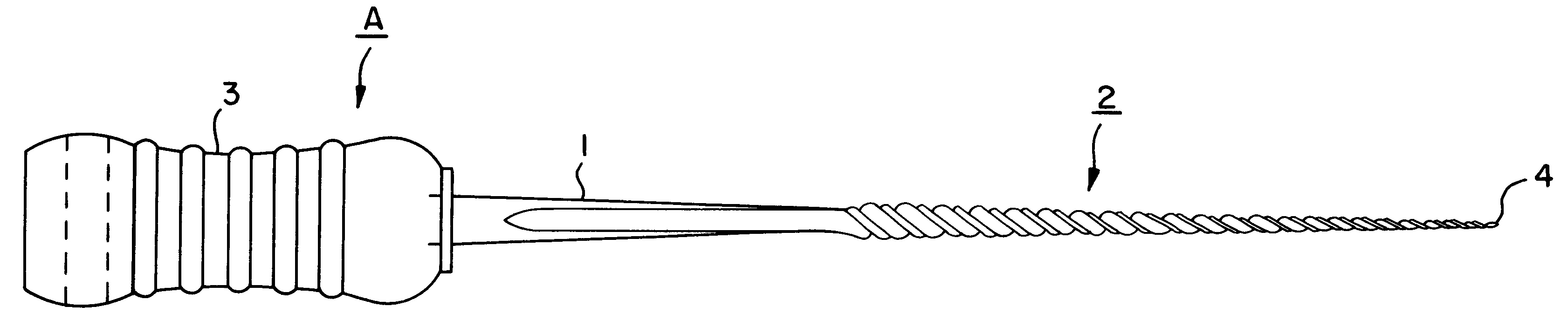
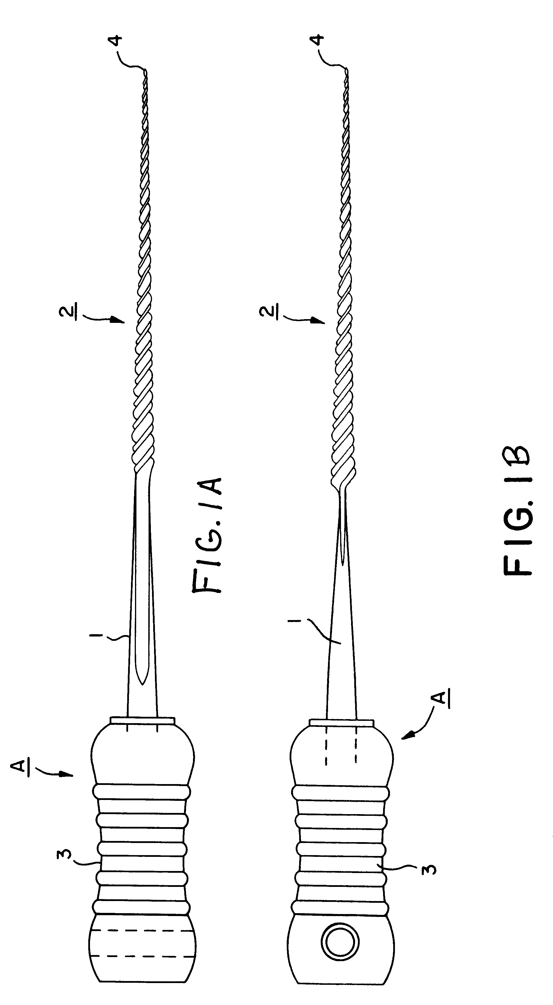
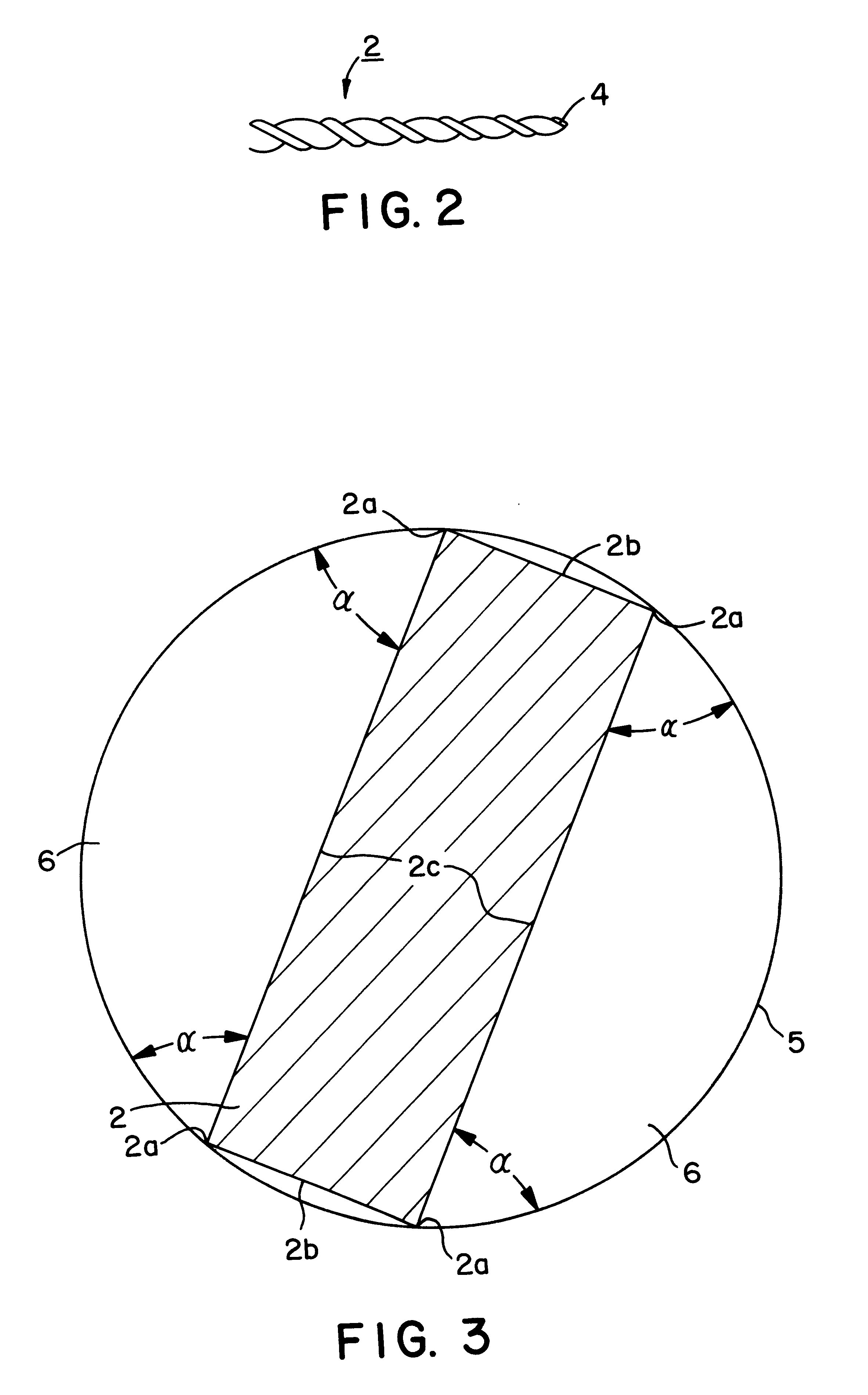
Referring to the drawings, endodontic instruments according to preferred embodiments of the invention are described. FIGS. 1(a), 1(b) are illustrations of an endodontic instrument according to a preferred embodiment of the invention wherein FIG. 1(a) is a front view of the endodontic instrument and FIG. 1(b) is a side view of the endodontic instrument; FIG. 2 is an enlarged view showing a tip portion of a work portion; FIG. 3 is an illustration showing a cross section of the work portion; and FIG. 4 is a diagram showing comparing results of endodontic instruments according to the embodiment and a conventional K files.

The endodontic instrument A is a tool for shaping a root canal by grinding the canal. The endodontic instrument A is provided with variations having plural diameters in a range of No. 6 in size (the thickness of a distal end is 0.06 mm) to No. 140 in size (the thickness of a distal end is 1.40 mm). This endodontic instrument is used for shaping root canals by grinding t...


PUM


Abstract

Present invention relates to an endodontic instrument comprising a shaft and a work portion connecting to the shaft. The work portion has a plurality of helically extending blades to form a rectangular cross section in which the opposite edges of one set are longer edges and the opposite edges of the other set are shorter edges, the work portion having each apex of a right angle.

Description

1. Field of the InventionThis invention relates to an endodontic instrument and, more particularly, to an instrument for treating a root canal such as a reamer, a file, or the like.2. Description of Related ArtA root canal in a tooth is very narrow and has a delicately curved shape, which is individually deviated greatly. A reamer and a file are generally used as an endodontic instrument for grinding and shaping such a root canal. The reamer and the file are cutting devices having blades extending in a spiral shape, in which contour connecting the apex extending in a tapered shape. The reamer is mainly controlled to rotate to grind the root canals while the file is mainly controlled to be pushed to grind the root canals. Among such files, there are K files having relatively small twisting angles but capable of grinding by rotation and H files having the largest twisting angle used exclusively for grinding by pushing.When a root canal therapy is made in use of, e.g., a file, a medica...

Claims


Application Information

Patent Timeline
IPC IPC(8): A61C5/02
CPCA61C5/023A61C5/42
Inventor KATSUUMI, ICHIROHMATSUTANI, KANJITAKASE, TOSHIYUKIMURAI, HIDEYUKI
Owner MANI INC
Why Eureka
Try Eureka