Device for clarifying a charged liquid by flotation

US6174435B1Inactive Publication Date: 2001-01-16KALTCHEV ROUMEN

Image

  • Device for clarifying a charged liquid by flotation
  • Device for clarifying a charged liquid by flotation
  • Device for clarifying a charged liquid by flotation

Examples


Embodiment Construction

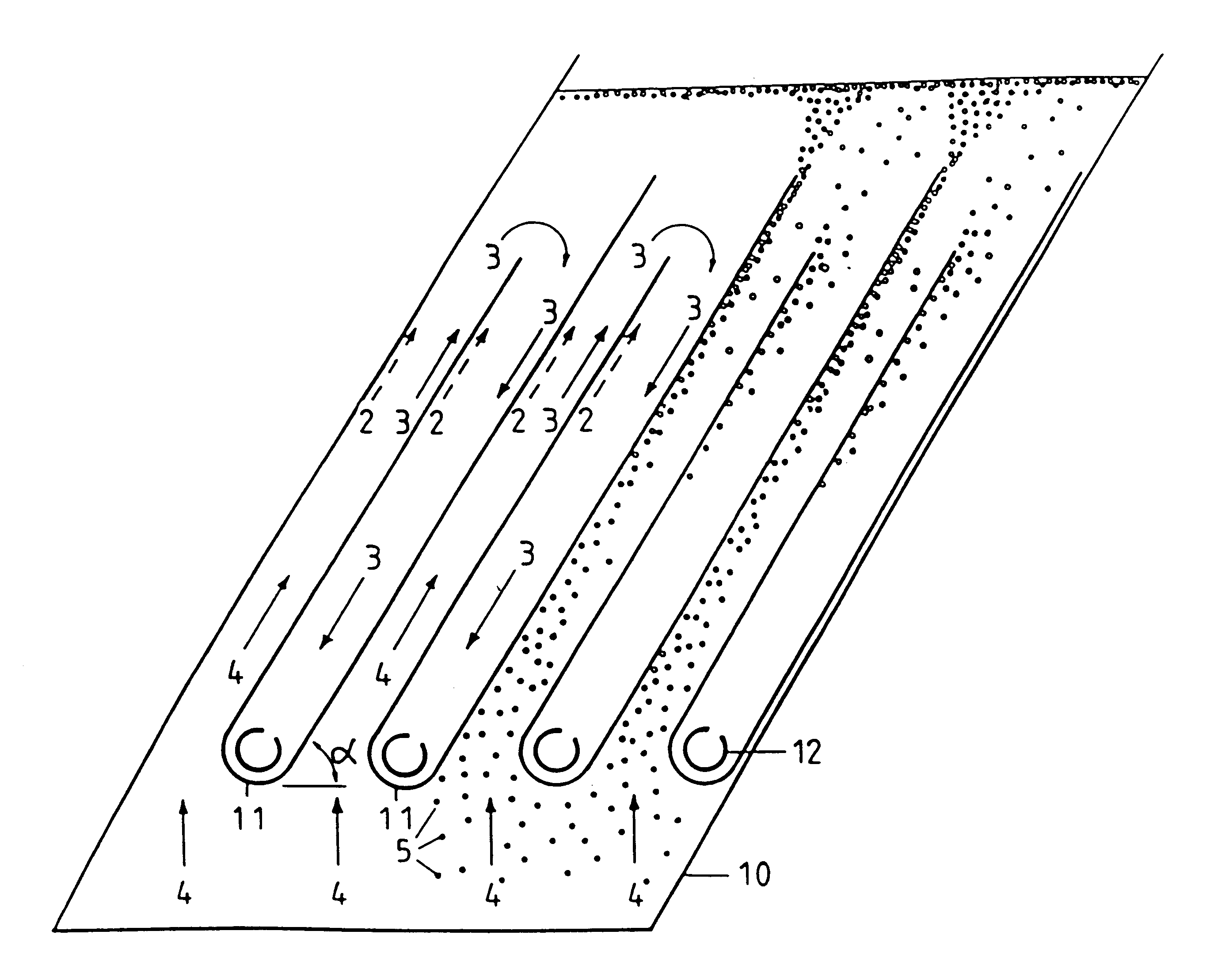
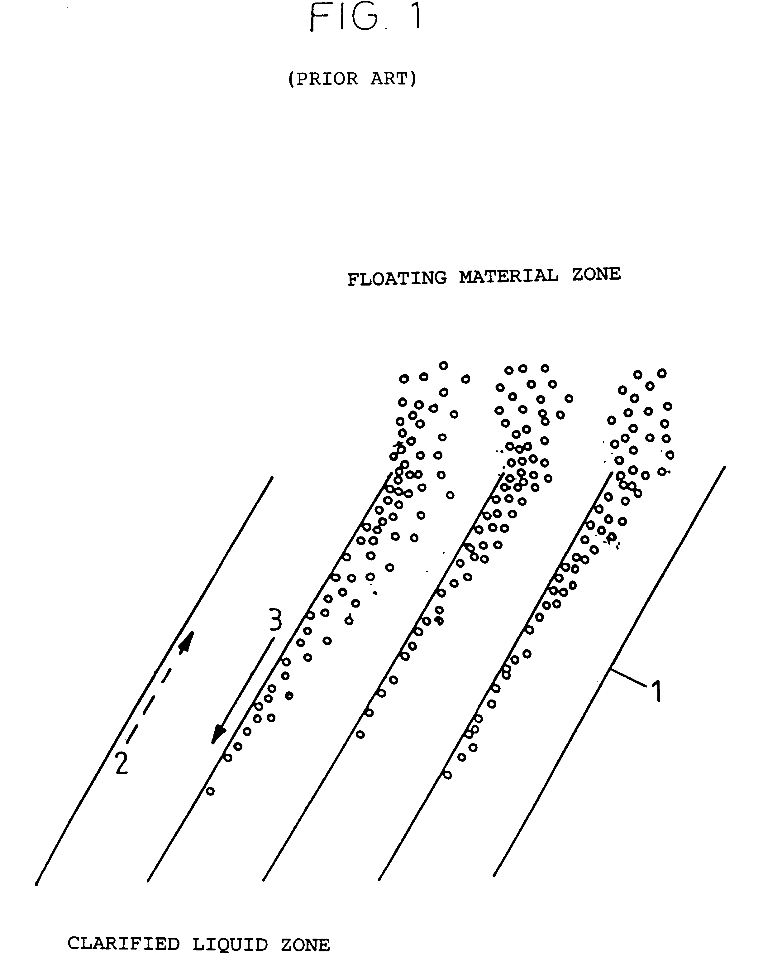
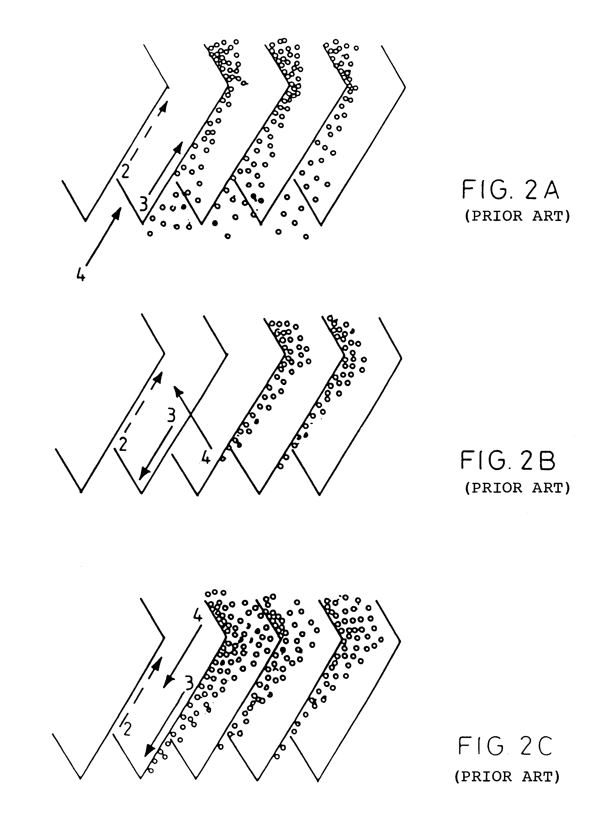
The device according to the invention makes it possible simultaneously to carry out two techniques of lamellar separation by flotation, operating in co-current and then in counter-current, respectively.

According to a first characteristic of the invention, the clarifier includes several (at least two) U-shaped components (11), inclined at an angle .alpha. relative to the horizontal, and immersed in the tank (10) as can clearly be seen in FIGS. 3A-3D, and thus positioned under the surface of the liquid. Each component (11) is equipped with a collector (12) placed at the base of the component on the side of its closed end. These collectors typically consist of a tubular component which is open along one of its generatrices. The components (11) are arranged in rows at a certain distance from each other.

The distance separating the two arms of each of the components (11) is chosen such that it is sufficient to allow a separation between the floating material (5) and the clarified liquid. ...


PUM

PropertyMeasurementUnit
Currentaaaaaaaaaa
Distanceaaaaaaaaaa
Distributionaaaaaaaaaa

Abstract

Apparatus for clarifying by flotation a liquid charged with a solid material that includes a tank for holding a quantity of liquid to be clarified. A plurality of U-shaped components are mounted in said tank below the level of the liquid in a relationship so each component is spaced apart a given distance from an adjacent component. Collectors are mounted in the base of each component to either introduce or remove liquid from the component to establish both a concurrent and countercurrent flow about the walls of the components.

Description

The invention relates to a device for clarifying by lamellar flotation. The device according to the invention can be used to accelerate the separation of materials in suspension, referred to hereinbelow by the abbreviation MIS, contained in a liquid, by natural flotation, if their density is less than that of the liquid. The invention can also be used in combination with the technique of flotation with dissolved air. In these two applications, the construction and the operating principle of the device according to the invention are the same.The common name for clarifiers of this type, using flotation and the lamellar technique, is an inclined-plate float or a lamellar float.The process and the device described are particularly designed to accelerate the separation of materials in suspension from a liquid effluent.PRIOR ARTThe existing devices of this type use the following techniques:A / The Technique of Lamellar Separation.This technique is used to accelerate the separation of the M...

Claims


Application Information

Patent Timeline
16 Jan 2001
Publication
US6174435B1
IPC
B01D21/00; B01D17/02; C02F1/24; B01D17/028; B01D17/035; B01D21/24; B01D21/28
CPC
B01D17/0205; B01D21/0027; B01D21/0045; B01D21/0057; B01D21/006; B01D21/24; B01D21/2405; B01D21/2427
Inventors
KALTCHEV, ROUMEN