
Telescopic tube joint

a telescopic tube and joint technology, applied in the direction of couplings, rod connections, manufacturing tools, etc., can solve the problems of excessive wear and short life of the outer tube plug (6)

Inactive Publication Date: 2001-01-30
CHENG KUN CHIA
View PDF5 Cites 56 Cited by
  • Summary
  • Abstract
  • Description
  • Claims
  • Application Information

AI Technical Summary

Problems solved by technology

However, disadvantages of the joint include:
1 the life of the outer tube plug (6) is short, as the rubber material ages quickly, becomes brittle and wears excessively after a period of time, and

Method used


Image

  • Telescopic tube joint
  • Telescopic tube joint
  • Telescopic tube joint

Examples


Embodiment Construction

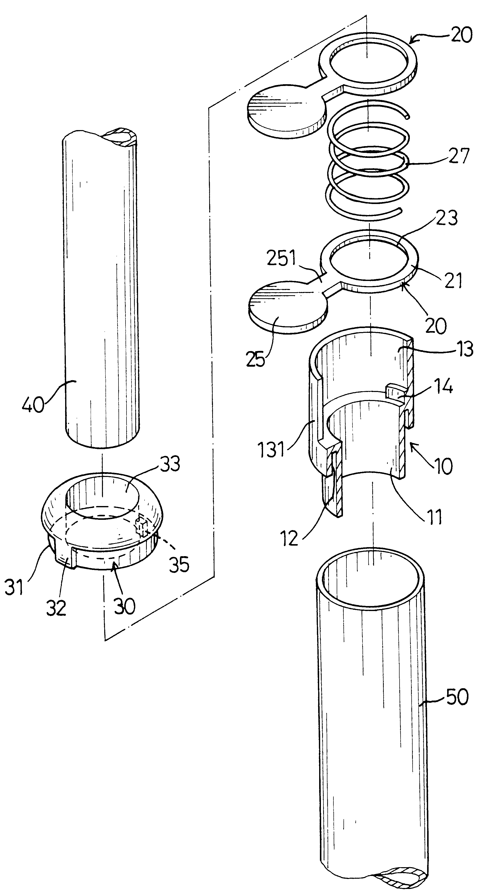
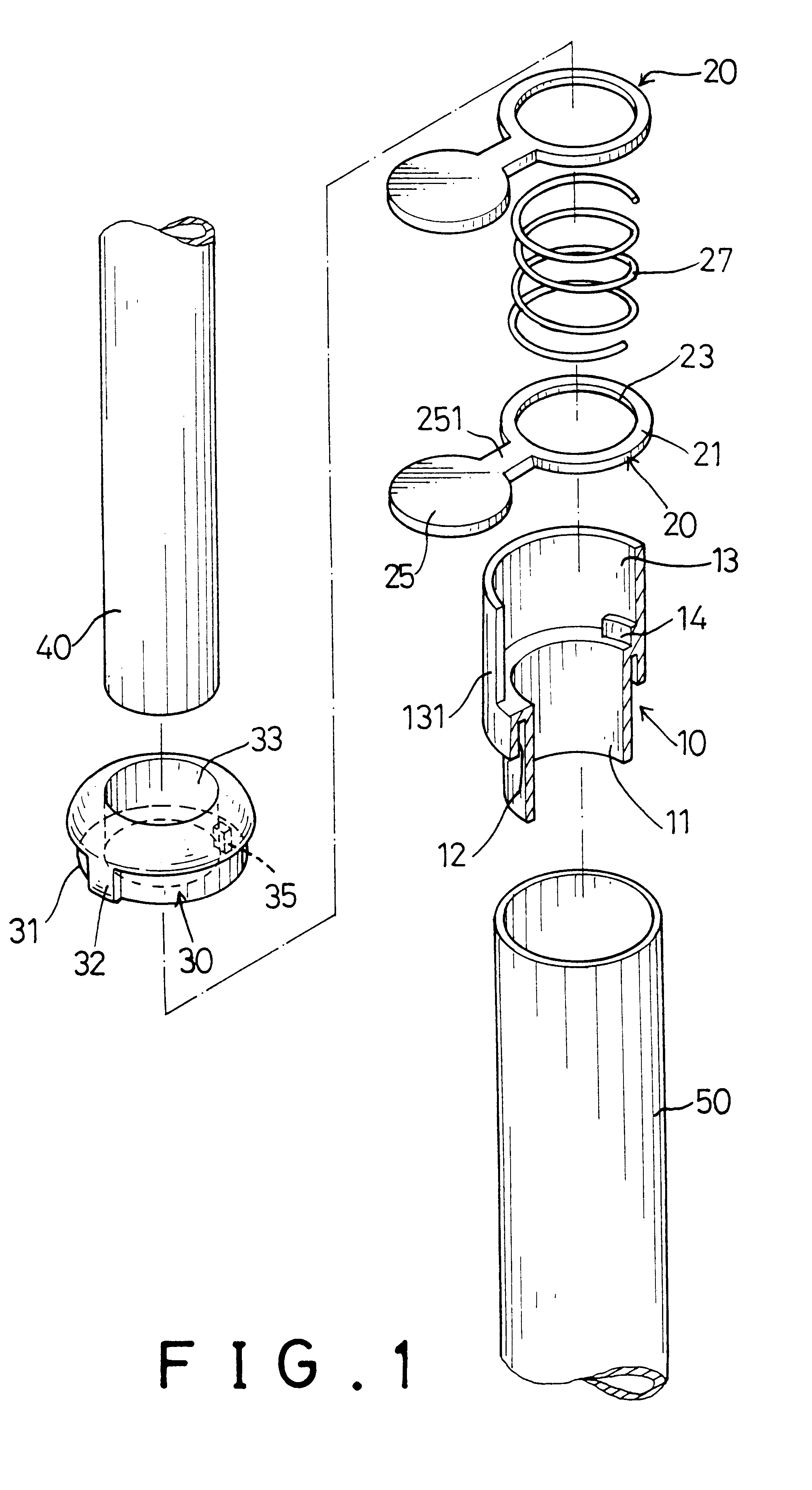
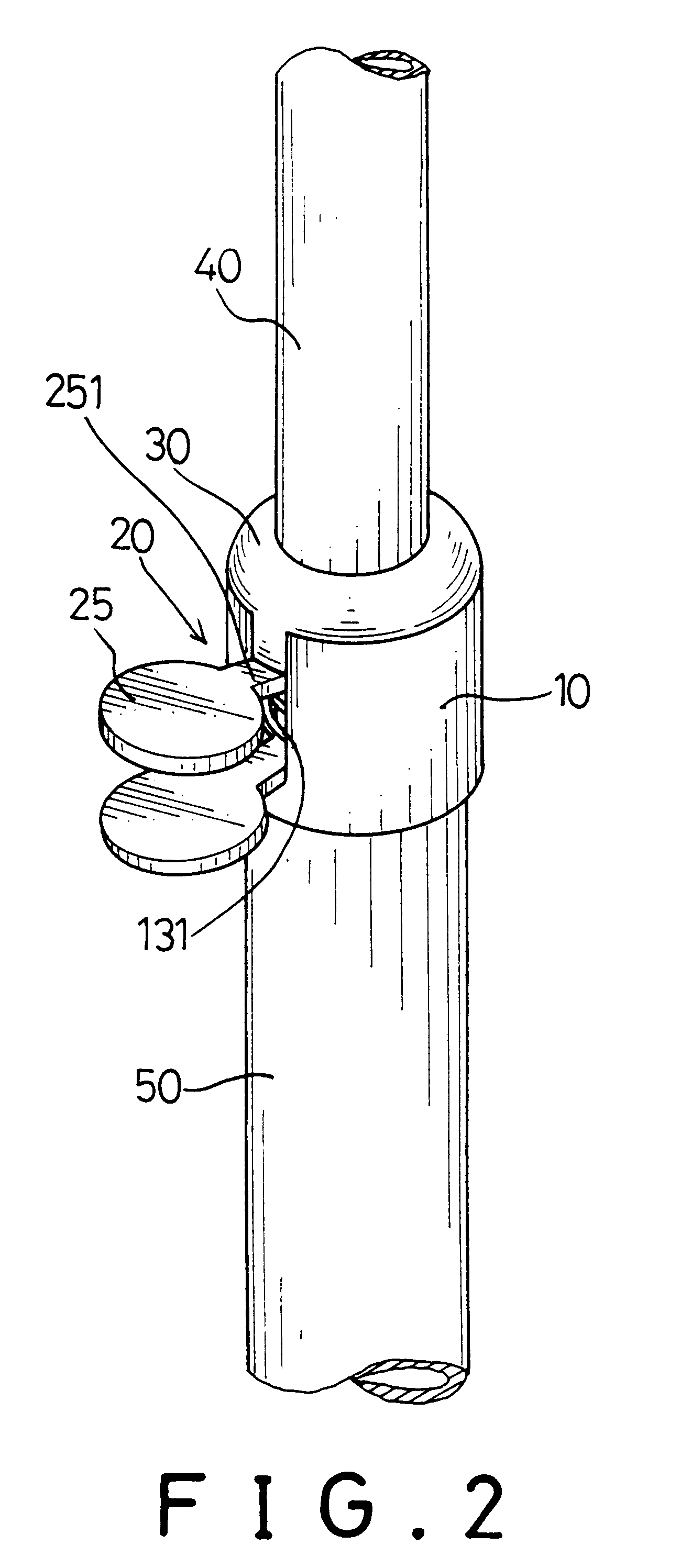
As shown in FIGS. 1 and 2, an inner tube (40) is adjustably fit into an outer tube (50) with a joint between the two tubes (40, 50), which comprises a sleeve (10), two locking rings (20) with a biasing member (27) between the two locking rings (20) and a sleeve cap (30).

The sleeve (10) is stepped with the diameter of one end larger than the other such that the small end can be press fit into the opening of the outer tube (50), and the open end of the outer tube (50) can be fixedly inserted into a longitudinal annular groove (12) formed by longitudinally extending the larger end of the sleeve (10). An inner bore (11) is defined in the sleeve (10) and has a diameter just large enough so that the inner tube (40) will slide freely. The other end of the sleeve (10) defines a locking chamber (13) with an open slot (131) communicating with the locking chamber (13). Furthermore, a ring step (14) is integrally formed on the inner wall of the sleeve (10) opposite the slot (131).

The locking ri...


PUM


Abstract

A telescopic tube joint has a sleeve, which is adapted to securely coupling an outer tube and an inner tube, and defines a locking chamber therein. At least two locking rings are received in the locking chamber of the sleeve, the locking rings are forced apart by a biasing member between the locking rings and cause the locking rings to press on the outer wall of the inner tube to hold the inner tube in place with respect to the outer tube. When a user squeezes the locking rings, the inner tube will slide freely in the outer tube.

Description

1. Field of the InventionThe present invention relates to an improved joint for securely connecting a pair of telescopic tubes.2. Description of Related ArtConventional telescopic tubes normally comprise an outer tube, an inner tube slidably received in the outer tube and joint between them to connect the inner tube and the outer tube. As shown in FIGS. 8 and 9, a compression joint between an inner tube (3) and an outer tube (4) comprises a rubber inner tube plug (5), a rubber outer tube plug (6), a stop sleeve (8) and a bolt (7) with an enlarged head (71). The inner tube plug (5) defines an offset axial threaded hole (52) and a flange (51) formed on the bottom. The diameter of the inner tube plug (5) is the same as the inside diameter of the inner tube (3), and the diameter of the flange (51) is the same as the outside diameter of the inner tube (3) so that the inner tube plug (5) is stopped by the open end of the inner tube (3). The outer tube plug (6) defines an offset axial thro...

Claims


Application Information

Patent Timeline
IPC IPC(8): B25G3/10B25G3/00F16B2/24F16B2/20F16B7/00F16L37/08F16L37/00F16B7/14
CPCB25G3/10F16B2/246F16B7/14F16L37/08Y10S285/902Y10T403/7077Y10T403/32516Y10T403/32483Y10T403/32524Y10T403/60Y10T403/32467
Inventor CHENG, KUN-CHIA
Owner CHENG KUN CHIA
Features
  • Generate Ideas
  • Intellectual Property
  • Life Sciences
  • Materials
  • Tech Scout
  • Unparalleled Data Quality
  • Higher Quality Content
  • 60% Fewer Hallucinations
Learn More