Circuit breaking device

a circuit breaking device and circuit technology, applied in the direction of electrical devices, coupling device connections, transportation and packaging, etc., can solve the problems of complicated structure of the plug box and the possibility of accidental loss of the main body of the plug box

Inactive Publication Date: 2001-03-06
YAZAKI CORP
View PDF5 Cites 32 Cited by
  • Summary
  • Abstract
  • Description
  • Claims
  • Application Information

AI Technical Summary

Benefits of technology

a plug box including a circuit terminal connected to the open end of an electric circuit; and, a plug main body including a short-circuit terminal and disposed in such a manner that it can be shifted by a given amount with respect to the plug box, the plug main body being able not only to bring the short-circuit terminal into fit with the circuit terminal of the plug box to thereby close the electric circuit but also to remove the short-circuit terminal from the circuit terminal to thereby open the electric circuit and thus cut off the circuit current of the electric circuit,
According to the present structure, since the locking arm can be protected by the arm protective walls, there can be prevented the possibility that an undesired external force can be applied directly to the lock arm to thereby damage the same.

Problems solved by technology

Therefore, there is a fear that the fingertips of the operator or a conductive part (a wire or the like) can be inserted into the terminal insertion hole by mistake to thereby come into contact with the circuit terminal provided within the plug box.
In order to prevent the operator's fingertips or conductive part from coming into direct contact with the circuit terminal, it is necessary to work the plug box specially, with the result that the structure of the plug box is complicated.
Also, since the plug main body pulled out of the plug box is separated completely from the plug box, there is a fear that the plug main body can be lost by accident.

Method used


Image

  • Circuit breaking device
  • Circuit breaking device
  • Circuit breaking device

Examples


Embodiment Construction

Now, description will be given below in detail of an embodiment of a circuit breaking device according to the invention with reference to the accompanying drawings.

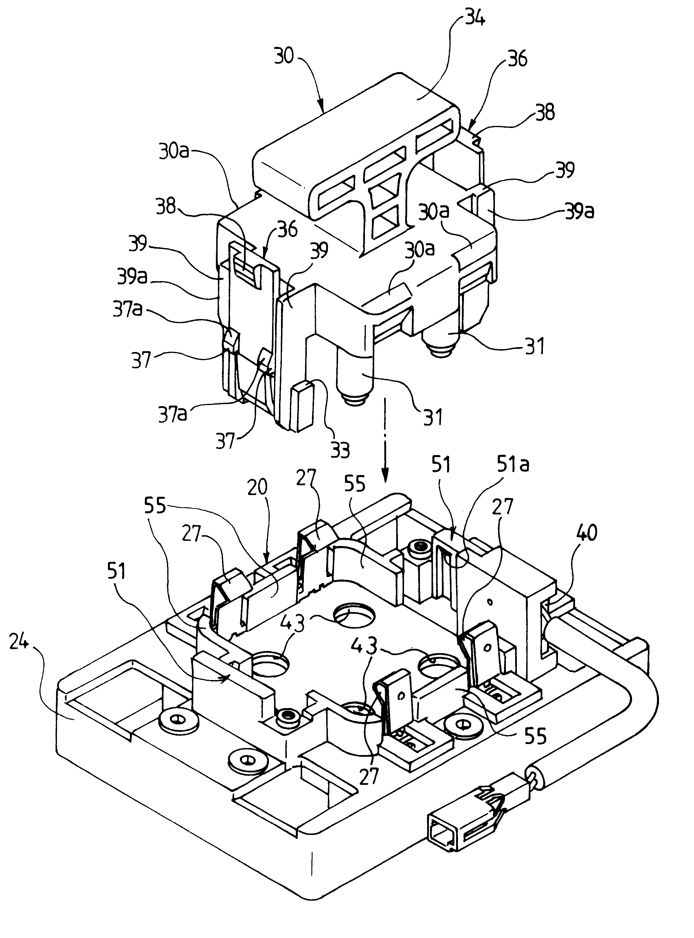
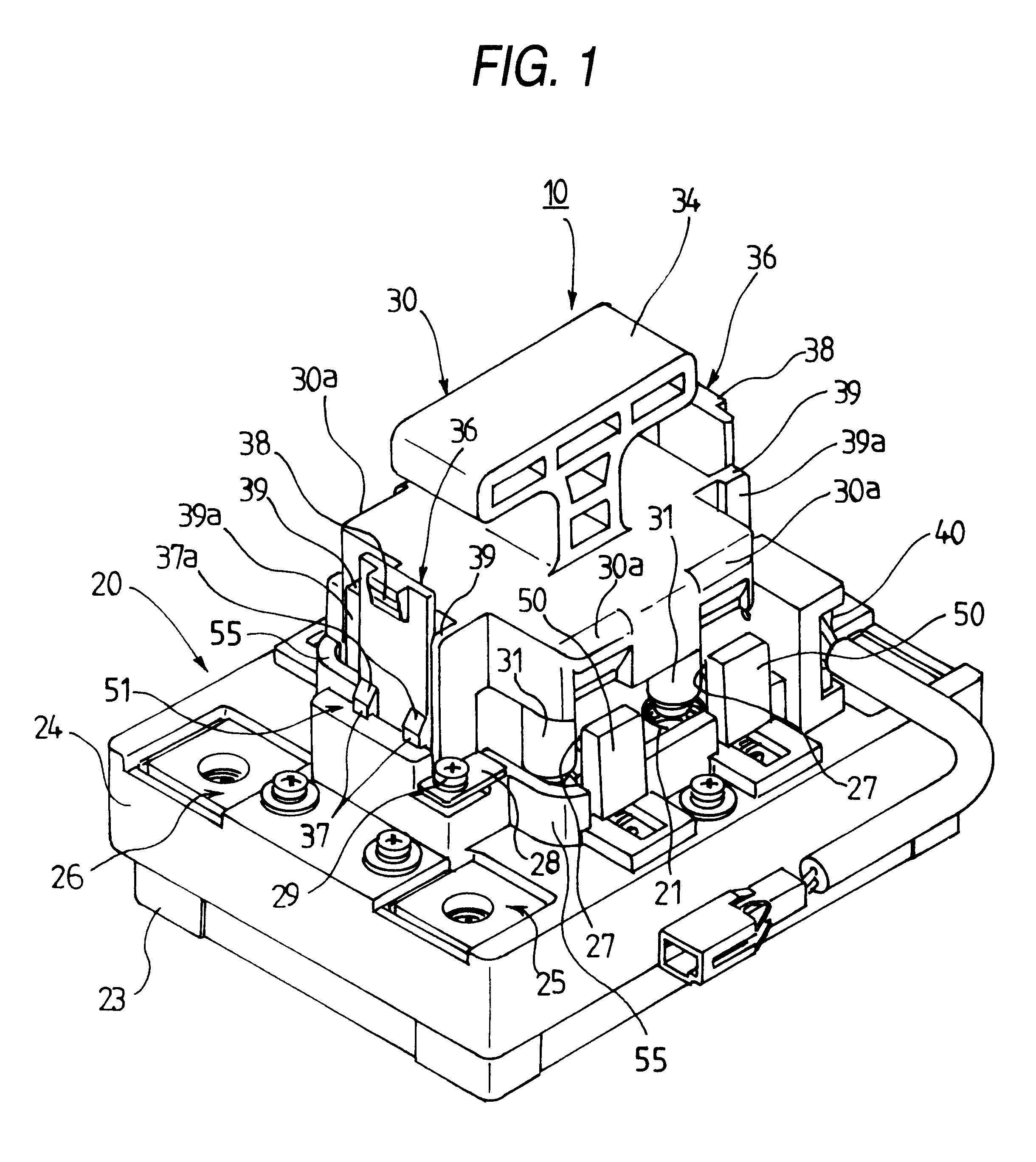
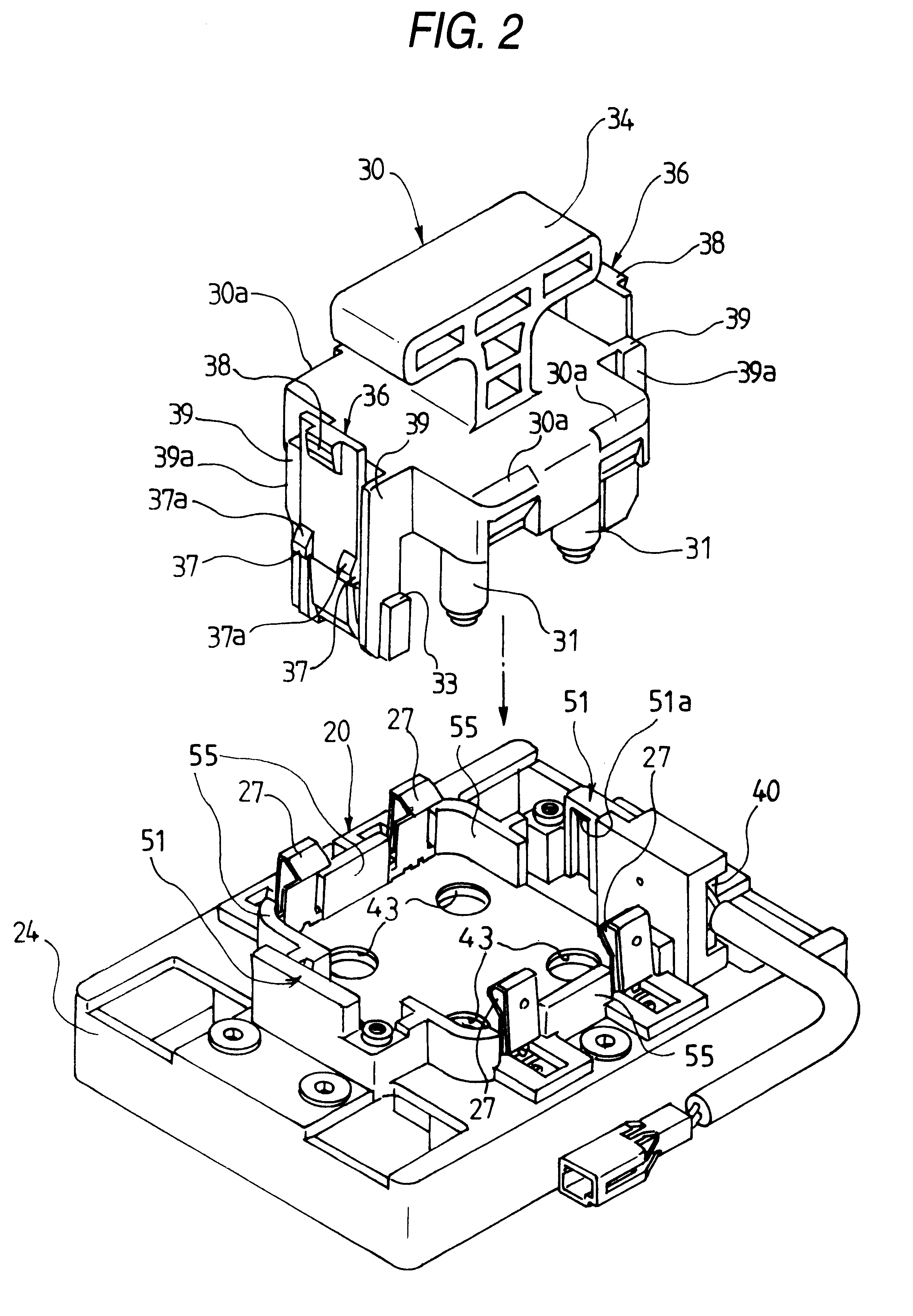
In particular, FIG. 1 is a perspective view of the whole structure of a circuit breaking device according to an embodiment of the invention, showing a temporarily secured state of the circuit breaking device; FIG. 2 is an exploded perspective view of the main portions of the circuit breaking device shown in FIG. 1; FIG. 3 is a plan view of the circuit breaking device shown in FIG. 1; FIG. 4 is a section view taken along the arrow line A--A shown in FIG. 3; FIG. 5 is a section view taken along the arrow line B--B shown in FIG. 3; FIG. 6 is a longitudinal section view of the circuit breaking device shown in FIG. 1, showing an actually secured state thereof; FIG. 7 is a section view taken along the arrow line C--C shown in FIG. 3; and, FIG. 8 is a section view of a plug main body shown in FIG. 7, taken along the arrow line D...


PUM


Abstract

The circuit breaking device 10 includes a plug box 20 including circuit terminals 21 and 22 respectively connected to the respective open ends of two electric circuits, and a plug main body 30 including short-circuit terminals 31, 32 and disposed in such a manner that it can be shifted by a given amount with respect to the plug box 20; in particular, the plug main body 30 is structured such that not only it can bring the short-circuit terminals 31 and 32 into fit with the circuit terminals 21 and 22 of the plug box 20 to thereby close the two electric circuits, but also it can remove the short-circuit terminals 31 and 32 from the circuit terminals 21 and 22 to thereby open the two electric circuits and thus cut off the circuit currents thereof. The plug main body 30 is allowed to shift with respect to the plug box 20 between the actually securing position where the short-circuit terminals 31, 32 can be fitted with the circuit terminals 21, 22 and the temporarily securing position where the short-circuit terminals 31, 32 can be removed from the circuit terminals 21, 22.

Description

1. Field of InventionThe present invention relates to a circuit breaking device and, in particular, to a circuit breaking device which, when checking and maintaining an electric car, a hybrid car or a similar car which includes a high-voltage circuit used to drive a motor, can cut off the circuit current of the high-voltage circuit temporarily.2. Related ArtIn recent years, when checking and maintaining a car such as an electric car, a hybrid car or a similar car which is in the spotlight as a low-pollution car and includes a high-voltage circuit used to drive a motor, in order to prevent an operator from getting an electric shock, it is necessary to cut off the circuit current of the high-voltage circuit temporarily.In view of this, in a conventional electric car or the like, as a circuit breaking device for cutting off the circuit current of a high-voltage circuit temporarily, there is proposed a circuit breaking device which comprises a plug box including a circuit terminal conne...

Claims


Application Information

Patent Timeline
Patent Type & Authority Patents(United States)
IPC IPC(8): H01H9/00H01H9/08H01R13/627H01R13/68B60R16/02H01H31/24H01R31/08
CPCB60L3/00H01H9/085H01R13/6272H01R13/68H01H2009/108
Inventor MATSUMOTO, MITSUHIRODENO, MASAHIRO
Owner YAZAKI CORP
Why Eureka
Try Eureka