Paint bucket with integral grate

a technology of grate and bucket, applied in the field of grates, can solve the problems of not being able to discount the cost of the grates as part of the cost of a painting job, the painters rarely reuse the grates after completing a job, and the inconvenience of using the grate and bucket as described abov

Inactive Publication Date: 2001-03-13
ELLIS ROBERT S
View PDF10 Cites 56 Cited by
  • Summary
  • Abstract
  • Description
  • Claims
  • Application Information

AI Technical Summary

Problems solved by technology

Using a grate and bucket as described above is often annoying because grates tend to slip off the bucket rims and slide into the buckets.
Furthermore, painters rarely reuse the grates after completing ...

Method used


Image

  • Paint bucket with integral grate
  • Paint bucket with integral grate
  • Paint bucket with integral grate

Examples


Embodiment Construction

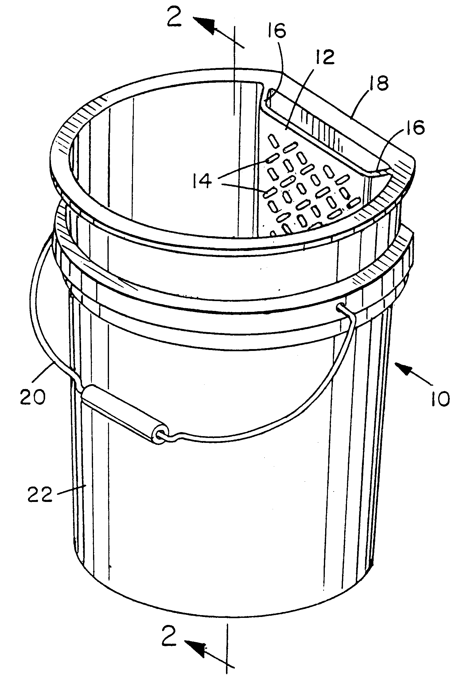
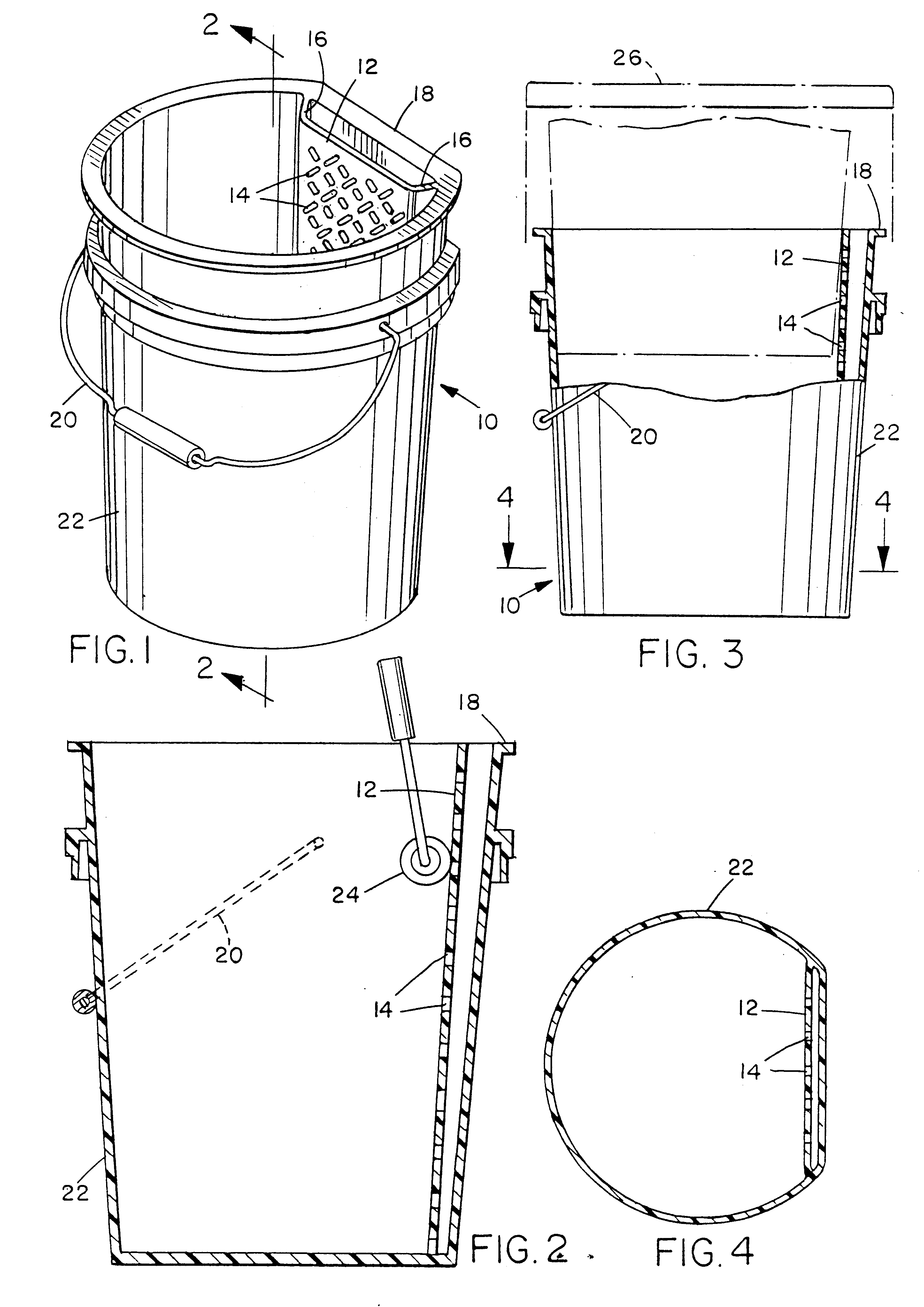
As illustrated in FIGS. 1-4, a plastic paint bucket has a cylindrical receptacle portion 10 unitarily formed, such as by molding or plastic welding, with a grate portion 12. The cylindrical shape tapers slightly and allows the bucket to nest with like buckets, as shown in FIG. 3. Grate portion 12 has a generally rectangular shape. Its surface has openings 14 but is otherwise flat or planar. The width of grate portion 12 is preferably at least 101 / 2 inches to accommodate the width of a standard paint roller. The top edge of grate portion 12 is even with the top of receptacle portion 10. The bottom edge of grate portion 12 is even with and adjoins the bottom of receptacle portion 10. Spacing portions 16, also unitarily formed with receptacle portion 10 and grate portion 12, adjoin the side edges of grate portion 12 along their length and space grate portion 12 from a sidewall 18 of receptacle portion 10. The spacing promotes drainage of paint that is squeezed through openings 14. Side...


PUM


Abstract

A plastic bucket or pail has a receptacle portion unitarily formed with a grate portion and can be used to apply paint or other suitable materials to a roller. One can squeeze excess paint from the roller by rolling it over the grate. The bucket may be included as part of an integral product in which paint is provided in a sealed bucket.

Description

1. Field of the InventionThe present invention relates generally to painting tools and, more specifically, to grates for removing excess paint from a roller.2. Description of the Related ArtA painter often uses a roller brush to apply paint. Typically, the paint is purchased in one-gallon cans or, for larger commercial jobs, two or five-gallon plastic buckets. A painter can apply paint to a roller either by rolling the roller brush in a shallow tray that has been filled with paint or by dipping it into a bucket. The painter then rolls the roller against a grate or similar flat surface, which may either be integrally formed in a tray bottom or may be a separate screen or grate. Such a grate is typically made of metal screening. When applying paint from a bucket, the painter inserts the grate into the bucket and props it against the wall of the bucket. The upper edge of the grate may have a hook that can be hung over the bucket rim to stabilize it. The painter dips the roller into the...

Claims


Application Information

Patent Timeline
IPC IPC(8): B44D3/12
CPCB44D3/126
Inventor ELLIS, ROBERT S.
Owner ELLIS ROBERT S
Why Eureka
Try Eureka