Apparatus and method for pilot-tube guided auger boring

a technology of guided auger boring and apparatus, which is applied in the direction of shaft sinking, shaft equipment, artificial islands, etc., can solve the problems of limited pipe installation maximum diameter, inconvenient installation, and inability to meet the requirements of the installation process,

Inactive Publication Date: 2001-03-27
EXACTGRADE UNDERGROUND INFRASTRUCTURE
View PDF6 Cites 37 Cited by
  • Summary
  • Abstract
  • Description
  • Claims
  • Application Information

AI Technical Summary

Problems solved by technology

The line and grade control systems for auger boring, however, is not very precise.
A problem with the pilot-bore microtunnelling method is that it is limited in the maximum diameter of pipe installable (to appro...

Method used


Image

  • Apparatus and method for pilot-tube guided auger boring
  • Apparatus and method for pilot-tube guided auger boring
  • Apparatus and method for pilot-tube guided auger boring

Examples


Embodiment Construction

Reference will now be made in detail to the preferred embodiment of the present invention, an example of which is illustrated in the accompanying figures. Whenever possible, the same reference numbers will be used throughout the description and figures to refer to the same or like parts.

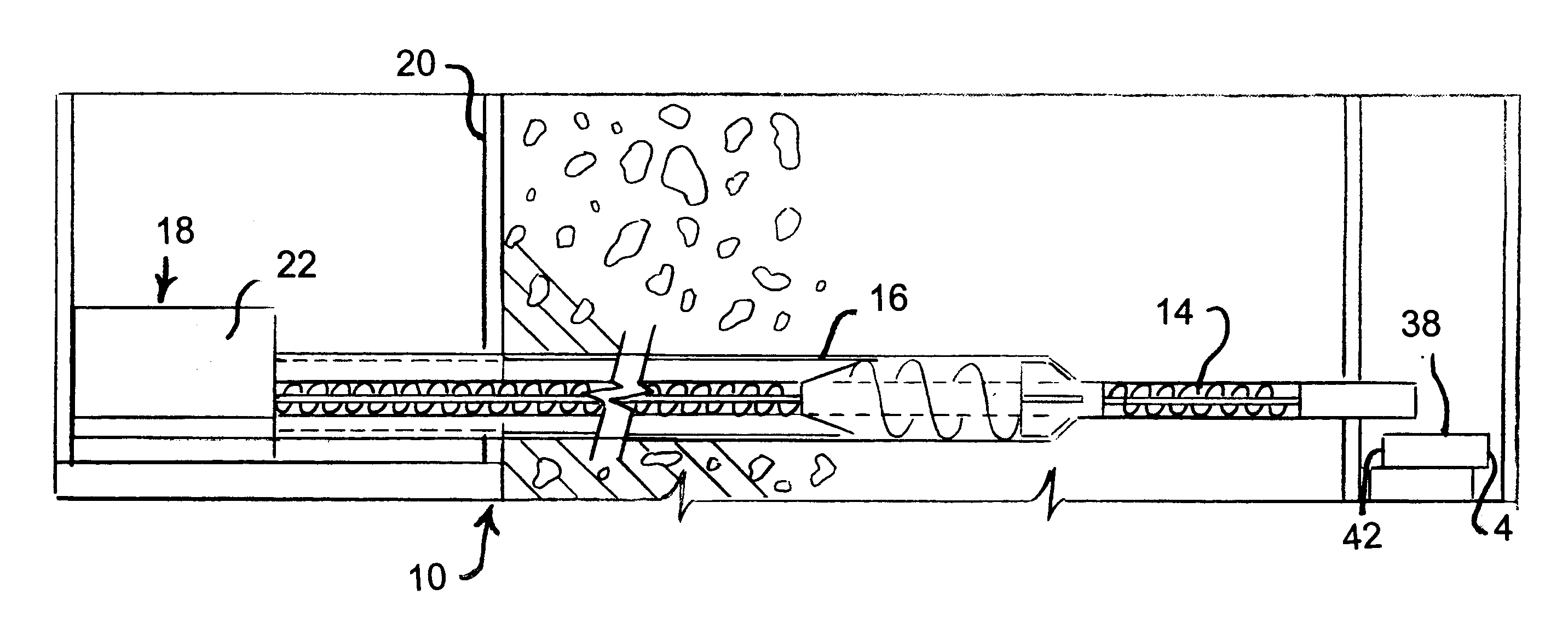
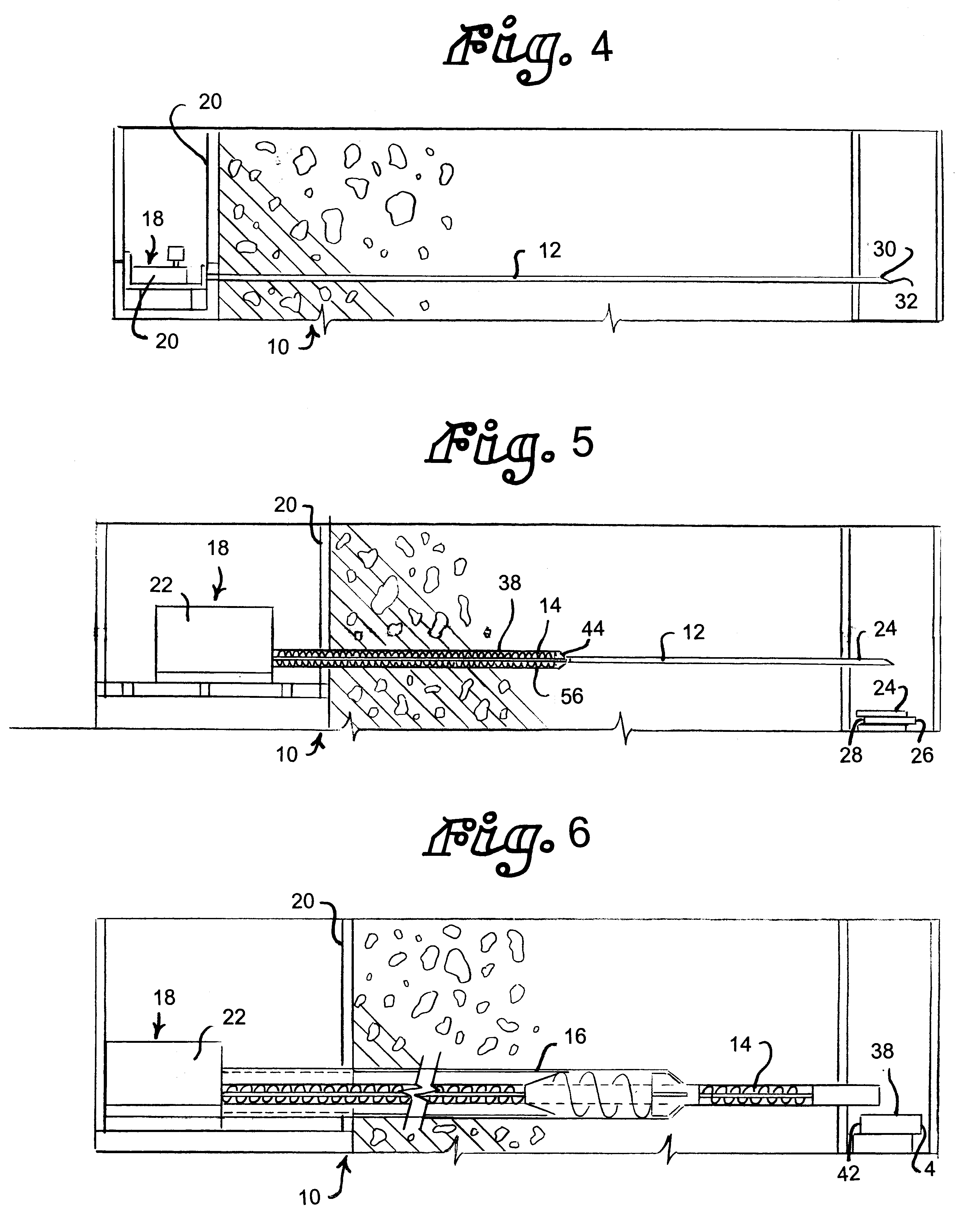
An apparatus for trenchless, underground emplacement of product casing between first and second shaft locations is indicated generally at 10 in FIGS. 4-6. The apparatus 10 comprises a pilot assembly 12, an intermediate assembly 14, an enlarging assembly 16, and a multi-stage drive assembly, indicated generally at 18. The drive assembly 18 is positioned in the first shaft location or drive pit 20 for successively advancing the assemblies into and through the desired underground location and installing product pipe in the remaining bore.

The multi-stage drive assembly 18 includes a microtunneling pipe-driving unit 20, such as the RVS 80 from Soltau Microtunneling Inc. of Charleston, S.C., for advancing ...


PUM


Abstract

An apparatus and method for trenchless, underground emplacement of man-sized product pipe between first and second shaft locations is disclosed. The apparatus comprises a pilot tube assembly having a pilot tube segment and a steering head mounted to the pilot tube segment. The steering head is configured to operatively guide the pilot tube assembly from the first shaft location to the second shaft location. The apparatus further comprises an intermediate sleeve assembly having an intermediate sleeve segment and an intermediate cutting head mountable to the pilot tube assembly and to the sleeve segment. The intermediate cutting head has a diameter substantially greater than the diameter of the pilot tube assembly and is configured to be operably guided by the pilot tube assembly. An enlarging assembly of the apparatus comprises a drive sleeve segment and an enlarging cutting head mounted to the intermediate sleeve assembly and to the drive sleeve segment. The enlarging cutting head has a diameter substantially larger than the diameter of the intermediate sleeve assembly and the drive sleeve segment. The enlarging cutting head and the drive sleeve segment are operably guidable by the intermediate sleeve assembly. A drive assembly successively advances the pilot tube assembly, the intermediate sleeve assembly, the trailing assembly, and product pipe from the first shaft location to the second shaft location.

Description

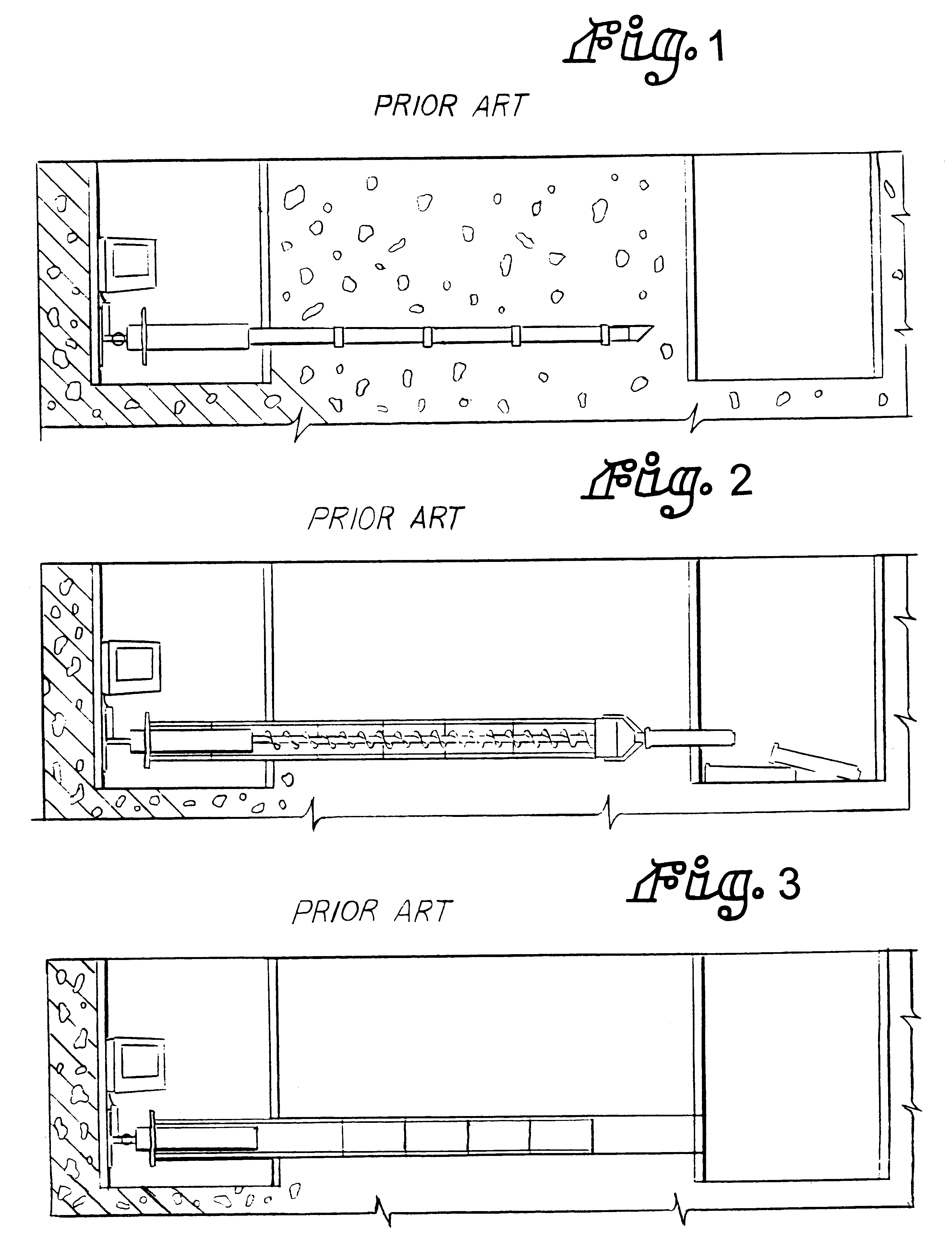
1. Field of the InventionThis invention relates generally to an apparatus and method for underground pipe installation and, more particularly to an apparatus and method for trenchless installation of product pipe through pilot-tube guided, auger boring.2. Discussion of Related ArtVarious applications require the installation of underground pipe between two stations without creating a trench therebetween, such as between two manholes. Techniques have been developed to accomplish such trenchless installation of pipe. Most of these methods are based on pipe-jacking principles, that is, protective pipes or product pipes are jacked through the ground by means of a hydraulically operated jacking unit from a previously prepared starting or jacking shaft to a target shaft. For example, one method for installing product pipes of non-man-sized nominal diameters in such an environment is shown and described in U.S. Pat. No. 4,630,967 and DE-GmS No. 82-05-543, the teachings of which are incorpo...

Claims


Application Information

Patent Timeline
IPC IPC(8): E21B7/00E21B7/28E21B7/20
CPCE21B7/201E21B7/28
Inventor MONIER, DAVID J.ROBINSON, FRANCIS E.
Owner EXACTGRADE UNDERGROUND INFRASTRUCTURE
Why Eureka
Try Eureka