
Snare for endoscope

a technology of endoscope and snare, which is applied in the field of snare, can solve problems such as affecting the treatment of polyps

Inactive Publication Date: 2001-05-01
ASAHI KOGAKU KOGYO KK
View PDF11 Cites 70 Cited by
  • Summary
  • Abstract
  • Description
  • Claims
  • Application Information

AI Technical Summary

Problems solved by technology

This may hinder the polyp excision treatment.

Method used


Image

  • Snare for endoscope
  • Snare for endoscope
  • Snare for endoscope

Examples


Embodiment Construction

Embodiments of the present invention will be described below with reference to the accompanying drawings.

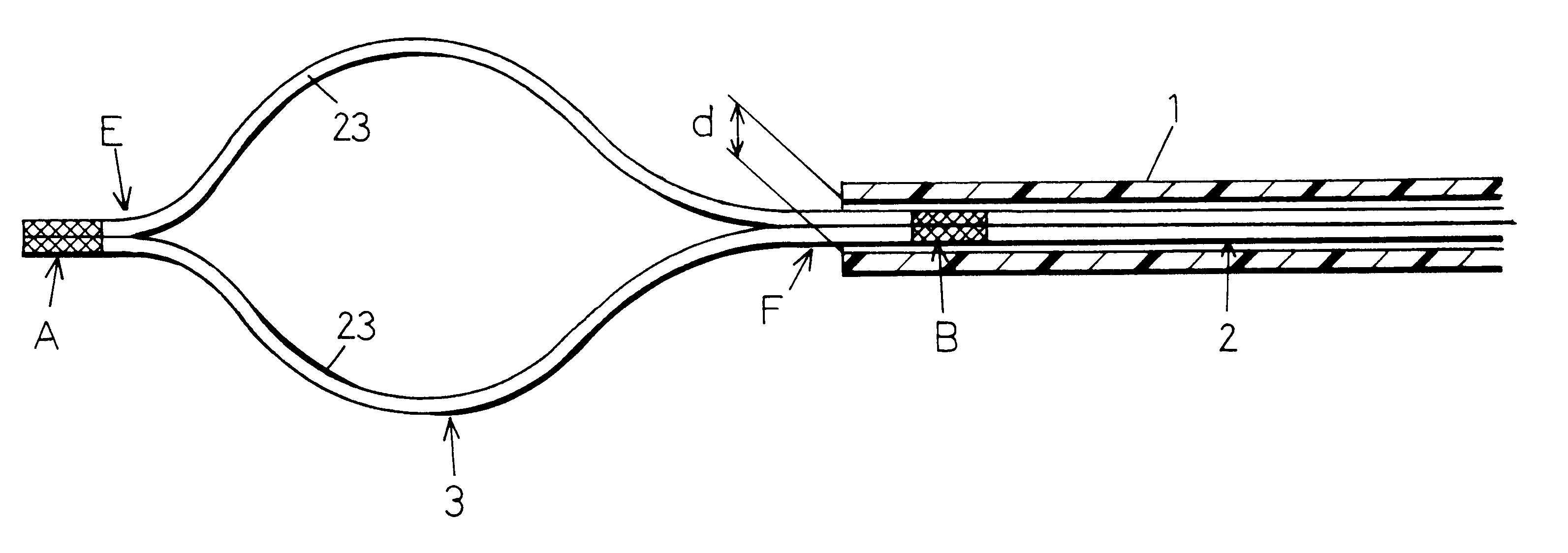
FIG. 1 shows a distal end portion of a snare for an endoscope according to a first embodiment of the present invention. A flexible sheath 1 is formed from a tetrafluoroethylene resin tube, for example. The flexible sheath 1 is removably inserted into an instrument-inserting channel of an endoscope (not shown).

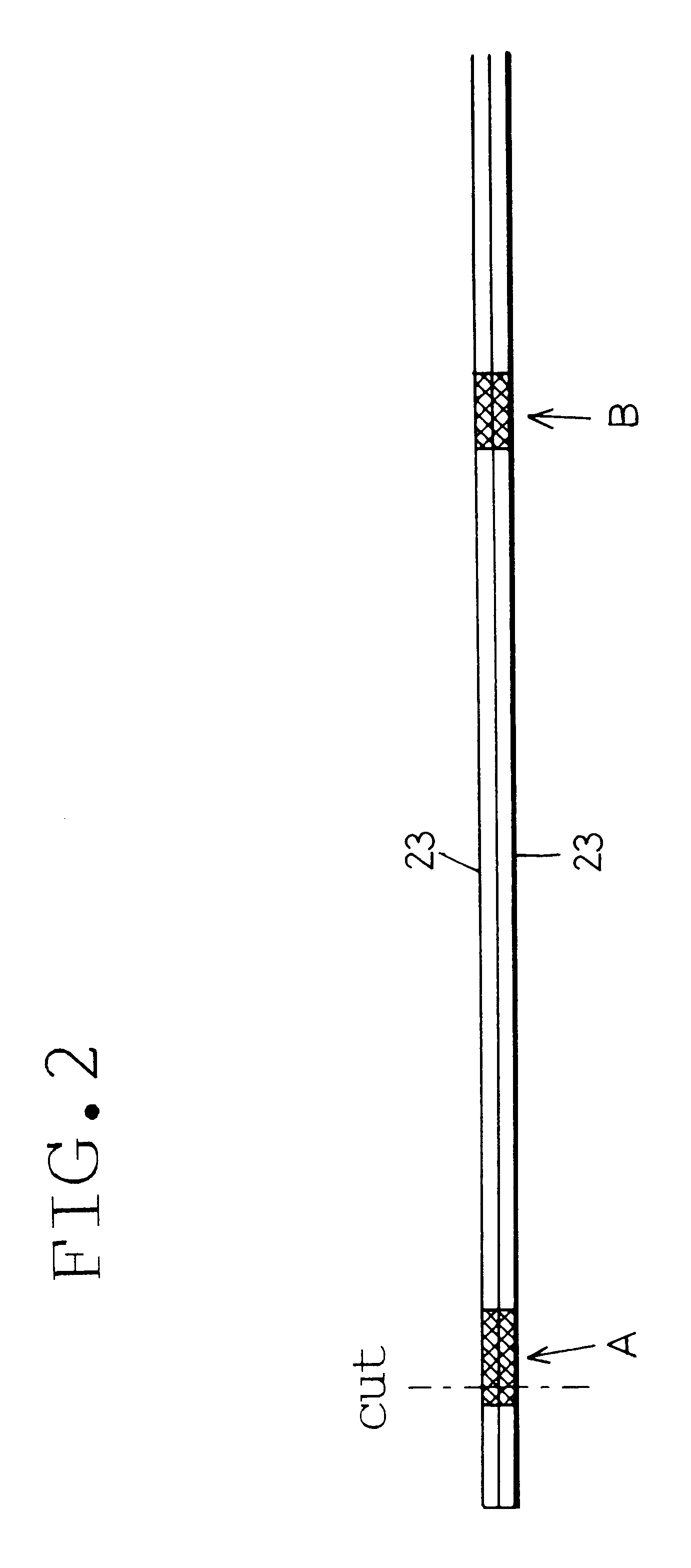
A snare loop 3 is formed by two electrically conductive elastic wires 23. Under conditions where no external force is applied thereto, the snare loop 3 forms a smoothly curved loop with a diameter of several centimeters. As each elastic wire 23, a single or stranded wire of stainless steel with a diameter of the order of from 0.2 mm to 0.5 mm is used by way of example.

The snare loop 3 can be folded by elastic deformation of the elastic wires 23 under application of external force. When the external force is removed, the snare loop 3 is returned to the original loop shape by ...


PUM


Abstract

A snare for an endoscope includes a control wire axially movably inserted in a flexible sheath. A snare loop formed by an elastic wire is connected to the distal end of the control wire. When the control wire is advanced, the snare loop projects from the distal end of the sheath and expands in a loop shape by its own elasticity. When the control wire is retracted, the snare loop is pulled into the sheath and folded. The snare loop is formed by two elastic wires between two mutually secured portions of the elastic wires, which are laid in parallel and in close contact with each other and secured together directly at two longitudinally spaced positions. The control wire is formed by an extending portion of at least one of the elastic wires that extends rearward from the mutually secured portion at the rear end of the snare loop.

Description

The present disclosure relates to subject matter contained in Japanese Patent Application No. 10-259775 (filed on Sep. 14, 1998), which is expressly incorporated herein by reference in its entirety.1. Field of the InventionThe present invention relates to a snare that is inserted into an instrument-inserting channel of an endoscope to excise a polyp.2. Description of the Prior ArtFIG. 5 shows a distal end portion of a conventional snare for use with an endoscope. In a flexible sheath 1, a control wire 2 is axially movably inserted, and a snare loop 3 formed by an elastic wire is connected to the distal end of the control wire 2 through a connecting pipe 4.At the distal end of the snare loop 3, a single elastic wire is bent back in a U-shape as shown in FIG. 5. Alternatively, two elastic wires are inserted into a binding pipe (not shown) so as to be secured together therein.By virtue of the above-described arrangement, the snare loop 3 projects from or withdraws into the distal end o...

Claims


Application Information

Patent Timeline
IPC IPC(8): A61B17/32A61B18/14A61B17/221
CPCA61B17/32056A61B18/14A61B2018/1407
Inventor OUCHI, TERUO
Owner ASAHI KOGAKU KOGYO KK
Features
  • Generate Ideas
  • Intellectual Property
  • Life Sciences
  • Materials
  • Tech Scout
  • Unparalleled Data Quality
  • Higher Quality Content
  • 60% Fewer Hallucinations
Learn More